TCP optimization configuration
Before configuring TCP optimization, apply the following basic configuration settings on the Citrix® ADC appliance:
Initial configuration:
enable ns feature LB IPv6PT
enable ns mode FR L3 USIP MBF Edge USNIP PMTUD
disable ns feature SP
disable ns mode TCPB
set lb parameter -preferDirectRoute NO
set lb parameter -vServerSpecificMac ENABLED
set l4param -l2ConnMethod Vlan
set rsskeytype -rsstype SYMMETRIC
set ns param -useproxyport DISABLED
<!--NeedCopy-->
Note
Restart the Citrix ADC appliance if you change the rsskeytype system parameter.
TCP termination
For Citrix ADC T1 to apply TCP optimization it needs to first terminate incoming TCP traffic. Towards this end, a wildcard TCP vserver should be created and configured to intercept ingress traffic and then forward it to the Internet router.
Static or dynamic routing environment
For environments with static or dynamic routing in place, vserver can rely on routing table info to forward packets towards internet router. Default route must point to the internet router and also routing entries for client subnets towards wireless router should be in place:
Example:
add lb vserver vsrv-wireless TCP * * -persistenceType NONE -Listenpolicy "CLIENT.VLAN.ID.EQ(100) && SYS.VSERVER(\"vsrv-wireless\").STATE.EQ(UP)" -m IP -cltTimeout 9000
add route 0.0.0.0 0.0.0.0 192.168.2.1
add route 10.0.0.0 255.0.0.0 192.168.1.1
<!--NeedCopy-->
VLAN-to-VLAN (PBR) environment
There are customer environments where subscriber traffic is segmented to multiple flows and needs to be forwarded to different routers based on incoming traffic parameters. Policy Based Routing (PBR) can be used to route packets based on incoming packet parameters, such as VLAN, MAC address, Interface, source IP, source port, destination IP address, and destination port.
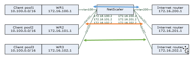
Example:
add lb vserver vsrv-wireless TCP * * -m IP -l2Conn ON -listenpolicy "CLIENT.VLAN.ID.EQ(100) || CLIENT.VLAN.ID.EQ(101) || CLIENT.VLAN.ID.EQ(102)"

add ns pbr pbr-vlan100-to-vlan200 ALLOW -vlan 100 -nexthop 172.16.200.1

add ns pbr pbr-vlan101-to-vlan201 ALLOW -vlan 101 -nexthop 172.16.201.1

add ns pbr pbr-vlan102-to-vlan202 ALLOW -vlan 102 -nexthop 172.16.202.1
<!--NeedCopy-->
Using Policy Based Routing to route TCP optimized traffic is a new feature added in release 11.1 50.10. For previous releases, having multiple “mode MAC” vserver entities per VLAN is an alternative solution for multi-VLAN environments. Each vserver has a bound service representing the internet router for the particular flow.
Example:
add server internet_router_1 172.16.200.1

add server internet_router_2 172.16.201.1

add server internet_router_3 172.16.202.1

add service svc-internet-1 internet_router_1 TCP * -usip YES -useproxyport NO

add service svc-internet-2 internet_router_2 TCP * -usip YES -useproxyport NO

add service svc-internet-3 internet_router_3 TCP * -usip YES -useproxyport NO

bind service svc-internet-1 -monitorName arp

bind service svc-internet-2 -monitorName arp

bind service svc-internet-3 -monitorName arp

add lb vserver vsrv-wireless-1 TCP * * -Listenpolicy "CLIENT.VLAN.ID.EQ(100) && SYS.VSERVER(\"vsrv-wireless-1\").STATE.EQ(UP)" -m MAC -l2Conn ON

add lb vserver vsrv-wireless-2 TCP * * -Listenpolicy "CLIENT.VLAN.ID.EQ(101) && SYS.VSERVER(\"vsrv-wireless-2\").STATE.EQ(UP)" -m MAC -l2Conn ON

add lb vserver vsrv-wireless-3 TCP * * -Listenpolicy "CLIENT.VLAN.ID.EQ(102) && SYS.VSERVER(\"vsrv-wireless-3\").STATE.EQ(UP)" -m MAC -l2Conn ON

bind lb vserver vsrv-wireless-1 svc-internet-1

bind lb vserver vsrv-wireless-2 svc-internet-2

bind lb vserver vsrv-wireless-3 svc-internet-3
<!--NeedCopy-->
Note:
The vserver mode is MAC in contrast to previous examples where it is mode IP. This is required to retain the destination IP information when we have service(s) bound to vserver. Also, the additional PBR configuration need to route non-optimized traffic.
TCP optimization
Out-of-the-box Citrix ADC TCP termination is configured for TCP pass-through functionality. TCP pass-through essentially means that Citrix ADC T1 may transparently intercept a client-server TCP stream but does not retain separate client/server buffers or otherwise apply any optimization techniques.
To enable TCP optimization a TCP profile, named as nstcpprofile, is used to specify TCP configurations that is used if no TCP configurations are provided at the service or virtual server level and it should be modified as follows:
Command:
add ns tcpProfile nstcpprofile -WS ENABLED -SACK ENABLED -WSVal 8 -mss 1460 -maxBurst 30 -initialCwnd 16 -oooQSize 15000 -minRTO 800 -bufferSize 4000000 -flavor BIC -dynamicReceiveBuffering ENABLED -KA ENABLED -sendBuffsize 4000000 -rstWindowAttenuate ENABLED -spoofSynDrop ENABLED -ecn ENABLED -frto ENABLED -maxcwnd 1000000 -fack ENABLED -rstMaxAck enABLED -tcpmode ENDPOINT
<!--NeedCopy-->
Note:
If there is not any profile explicitly created and bound to vserver and service, the profile nstcp_default_profile is bound by default.
In case of multiple TCP profiles requirement, extra TCP profiles can be created and associated with the appropriate virtual server
add ns tcpProfile custom_profile -WS ENABLED -SACK ENABLED -WSVal 8 -mss 1460 -maxBurst 30 -initialCwnd 16 -oooQSize 15000 -minRTO 800 -bufferSize 4000000 -flavor BIC -dynamicReceiveBuffering ENABLED -KA ENABLED -sendBuffsize 4000000 -rstWindowAttenuate ENABLED -spoofSynDrop ENABLED -ecn ENABLED -frto ENABLED -maxcwnd 1000000 -fack ENABLED -rstMaxAck enABLED -tcpmode ENDPOINT

set lb vserver vsrv-wireless -tcpProfileName custom_profile
<!--NeedCopy-->
Note:
For deployments with vserver -m MAC and service, same profile should be associated with service.
set service svc-internet -tcpProfileName custom_profile
<!--NeedCopy-->
TCP optimization capabilities
Most of the relevant TCP optimization capabilities of a Citrix ADC appliance are exposed through a corresponding TCP profile. Typical CLI parameters that should be considered when creating a TCP profile are the following:
- Window Scaling (WS): TCP Window scaling allows increasing the TCP receive window size beyond 65535 bytes. It helps improving TCP performance overall and specially in high bandwidth and long delay networks. It helps with reducing latency and improving response time over TCP.
- Selective acknowledgment (SACK): TCP SACK addresses the problem of multiple packet loss which reduces the overall throughput capacity. With selective acknowledgement the receiver can inform the sender about all the segments which are received successfully, enabling sender to only retransmit the segments which were lost. This technique helps T1 improve overall throughput and reduce the connection latency.
- Window Scaling Factor (WSVal): Factor used to calculate the new window size. It must be configured with a high value in order to allow the advertised window by NS to be at least equal to the buffer size.
- Maximum Segment Size (MSS): MSS of a single TCP segment. This value depends on the MTU setting on intermediate routers and end clients. A value of 1460 corresponds to an MTU of 1500.
- maxBurst: Maximum number of TCP segments allowed in a burst.
- Initial Congestion Window size(initialCwnd): TCP initial congestion window size determines the number of bytes which can be outstanding in beginning of the transaction. It enables T1 to send those many bytes without bothering for congestion on the wire.
- Maximum OOO packet queue size(oooQSize): TCP maintains Out Of Order queue to keep the OOO packets in the TCP communication. This setting impacts system memory if the queue size is long as the packets need to be kept in runtime memory. Thus this needs to be kept at optimized level based on the kind of network and application characteristics.
- Minimum RTO(minRTO): The TCP retransmission timeout is calculated on each received ACK based on internal implementation logic. The default retransmission timeout happens at 1 second to start with and this can be tweaked with this setting. For second retransmission of these packets RTO will be calculated by N*2 and then N*4 … N*8… goes on till last retransmission attempt.
- bufferSize / sendBuffsize: these refer to the maximum amount of data that the T1 may receive from the server and buffer internally without sending to the client. They should be set to a value larger (at least double) than the Bandwidth Delay Product of the underlying transmission channel.
- flavor: this refers to the TCP congestion control algorithm. Valid values are Default, BIC, CUBIC, Westwood and Nile.
- Dynamic receive buffering: allows the receive buffer to be adjusted dynamically based on memory and network conditions. It will fill up the buffer as much as it’s required to keep the client’s download pipe full instead of filling up, by reading ahead from server, a fixed size buffer, as latter is specified in TCP profile and typically based on criteria such as 2*BDP, for a connection. Citrix ADC T1 monitors the network conditions to the client and estimates how much it should read ahead from the server.
- Keep-Alive (KA): Send periodic TCP keep-alive (KA) probes to check if peer is still up.
- rstWindowAttenuate: Defending TCP against spoofing attacks. It will reply with corrective ACK when a sequence number is invalid.
- rstMaxAck: Enable or disable acceptance of RST that is out of window yet echoes highest ACK sequence number.
- spoofSynDrop: Drop of invalid SYN packets to protect against spoofing.
- Explicit Congestion Notification(ecn): It sends notification of the network congestion status to the sender of the data and takes corrective measures for data congestion or data corruption.
- Forward RTO-Recovery: In case of spurious retransmissions, the congestion control configurations are reverted to their original state.
- TCP maximum congestion window (maxcwnd): TCP maximum congestion window size that is user configurable.
- Forward acknowledgment (FACK): To avoid TCP congestion by explicitly measuring the total number of data bytes outstanding in the network, and helping the sender (either T1 or a client) control the amount of data injected into the network during retransmission timeouts.
- tcpmode: TCP optimization modes for specific profile. There are two TCP optimization modes - Transparent and Endpoint.
- Endpoint. In this mode, the appliance manages the client and server connections seperately.
- Transparent. In the transparent mode the clients need to access the servers directly, with no intervening virtual server. The server IP addresses must be public because the clients need to be able to access them.
Silently Dropping Idle Connections
In a Telco network, almost 50 percent of a Citrix ADC appliance’s TCP connections become idle, and the appliance sends RST packets to close them. The packets sent over radio channels activate those channels unnecessarily, causing a flood of messages that in turn cause the appliance to generate a flood of service-reject messages. The default TCP profile now includes DropHalfClosedConnOnTimeout and DropEstConnOnTimeout parameters, which by default are disabled. If you enable both of them, neither a half closed connection nor an established connection causes a RST packet to be sent to the client when the connection times out. The appliance just drops the connection.
set ns tcpProfile nstcpprofile  -DropHalfClosedConnOnTimeout ENABLED
set ns tcpProfile nstcpprofile  -DropEstConnOnTimeout ENABLED
<!--NeedCopy-->