Using USIP mode in cluster
In use source IP (USIP) mode, the cluster, or NetScaler appliance forwards each packet to the appropriate back-end server with the client IP address.
USIP mode traffic distribution
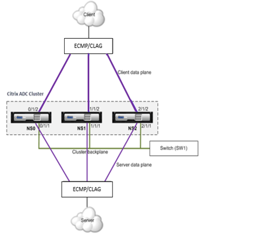
The USIP mode behavior differs traffic distribution across client data plane and server data plane in ECMP and CLAG deployment. The following section provides more information about USIP mode behavior. For more information related to CLAG on USIP mode, see Using cluster link aggregation.
USIP mode
The cluster uses the client IP to open the server-side connection. The source port may or might not be preserved based on the useproxyport setting.
USIP useproxyport scenarios
The USIP useproxyport is ON for the traffic flow, the source port is selected in a way that the reverse traffic hashes to the flow processor. It ensures single steering on the server side.
The USIP useproxyport is OFF for the traffic flow, the source port is preserved and hence there is double steering on the server side.
Important:
- When USIP is ON, the client IP is used in back end server connection, and traffic distribution for response is needed across cluster nodes. You can use ECMP or CLAG deployment for traffic distribution on the server side. In the absence of traffic distribution on the server side, the whole return traffic might land on a single cluster node, resulting in congestion.
- The
set rsskeytype –rsskey symmetriccommand is used to reduce double steering to single steering of traffic in theuseproxyportoff deployments. Where the 4-tuple for the connection remains the same for the server and client side. For example, wildcard MAC mode virtual server.
Limitations
The USIP does not work when the process local is disabled.
USIP mode deployment
The following figure depicts a USIP mode deployment in a cluster setup.

Configure the following using CLI
-
Enable the routing protocol.
enable ns feature <feature>Example:
enable ns feature ospf -
Add a spotted SNIP address for each node and enable dynamic routing on it.
add ns ip <SNIP> <netmask> -dynamicRouting \( ENABLED | DISABLED ) –ownerNode <positive\_interger> –ownerdownResponse \( YES | NO )Example
- add ns ip 192.0.2.1 255.255.255.0 -dynamicRouting ENABLED –ownerNode 0 –ownerDownResponse NO - add ns ip 192.0.2.2 255.255.255.0 -dynamicRouting ENABLED –ownerNode 1 –ownerDownResponse NO - add ns ip 192.0.2.3 255.255.255.0 -dynamicRouting ENABLED –ownerNode 2 –ownerDownResponse NO -
Add a VLAN.
add vlan <id>Example
add vlan 300 -
Bind the interfaces of the cluster nodes to the VLAN.
bind vlan <id> -ifnum <interface_name>Example
bind vlan 300 -ifnum 0/1/2 1/1/2 2/1/2 -
Bind one of the spotted SNIP addresses to the VLAN. When you bind one spotted SNIP address to a VLAN, all other spotted SNIP addresses defined on the cluster in that subnet are automatically bound to the VLAN.
bind vlan <id> -IPAddress <ip\_addr | ipv6\_addr> -netmaskExample
bind vlan 300 –IPAddress 192.0.2.1 255.255.255.0 -
Configure the routing protocol on ZebOS using the VTYSH shell. Configure OSPF routing protocol on node IDs 0, 1, and 2.
vtysh configure terminal ns block-sec-rtadv router ospf owner -node 0 router-id 192.0.2.1 exit-owner-node owner-node 1 router-id 192.0.2.2 exit-owner-node owner-node 2 router-id 192.0.2.3 exit-owner-node network 192.0.2.0/24 area 0 default-information originate always -
Perform the following configurations on the Cisco 3750 router by using the CLI.
Configure terminal
feature ospf
interface vlan300
no shutdown
ip address 192.0.2.100/24
Configure terminal
router ospf 1
router-id 192.0.2.100
network 192.0.2.0 0.0.0.255 area 0
Notes:
Traffic distribution on client and server need not be the same. For example, you can configure ECMP on the client side and CLAG on the server side or the opposite way.
Plan for extra capacity of the backplane as there is more steering overhead in the USIP deployment.
The Configuration related to CLAG and Monitor Static Route (MSR) must remain the same on the server side.
Traffic steering is more in the USIP mode deployments.