
Configuring layer 3 clustering
Understanding the L3 cluster
The demand to expand the high availability deployment and increase the scalability of the client traffic across different networks guided to establish the L3 cluster. The L3 cluster lets you group NetScaler appliances across individual subnets (L2 cluster).
The L3 cluster is also referred as "cluster in Independent Network Configuration (INC) mode". In L3 cluster deployment, the cluster nodes in the same network are grouped to form a Node group. The L3 cluster uses GRE tunneling to steer the packets across networks. The heartbeat messages across the L3 clusters are routed.
Architecture
The L3 cluster architecture comprises the following components:
-
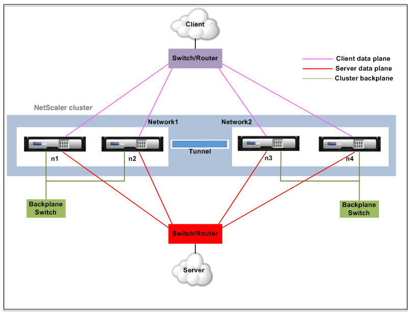
Nodegroup - The cluster nodes from each network (n1, n2) and (n3, n4), as shown in the following figure, are grouped to form a Node group. These Node groups are terminated to the layer 3 switch on either side of the network.
-
The cluster communicates with the client through the physical connections between the cluster node and the client-side connecting device. The logical grouping of these physical connections is called the client data plane.
-
The cluster communicates with the server through the physical connections between the cluster node and the server-side connecting device. The logical grouping of these physical connections is called the server data plane.
-
-
Backplane Switch - Cluster nodes within the same network communicate with each other by using the cluster backplane. The backplane is a set of interfaces in which one interface of each node is connected to a common switch, which is called the cluster backplane switch.
-
Tunnel - By default, the packets between nodes in a L3 cluster are exchanged over an unencrypted GRE tunnel that uses the NSIP addresses of the source and destination nodes for routing. The steering mechanism changes for nodes belonging to the different network. The packets are steered through a GRE tunnel to the node on the other subnet, instead of rewriting the MAC.Note:For a new deployment, we recommend using the UDP tunnel to steer the packets across nodes in different networks. The advantages of using a UDP tunnel are:
-
The steering between the packet engines is based on 4-tuple, which provides better distribution.
-
You can avoid the skewness in CPU utilization.
-
Starting from the 14.1-29.x release, jumbo frames are now supported for UDP tunnels. For UDP tunnels, an extra 42 bytes of overhead are required for steering. To avoid fragmentation among cluster nodes, make sure that the data interface MTU size is between 9198 bytes and 9215 bytes.
Refer to the following table to understand how packets are steered in different tunnel modes.Tunnel mode Same network Different network None A backplane is used to steer the packets. GRE tunnel is used to steer the traffic. GRE GRE tunnel is used to steer the packets. GRE tunnel is used to steer the packets. UDP UDP tunnel is used to steer the packets. UDP tunnel is used to steer the packets. -
Example
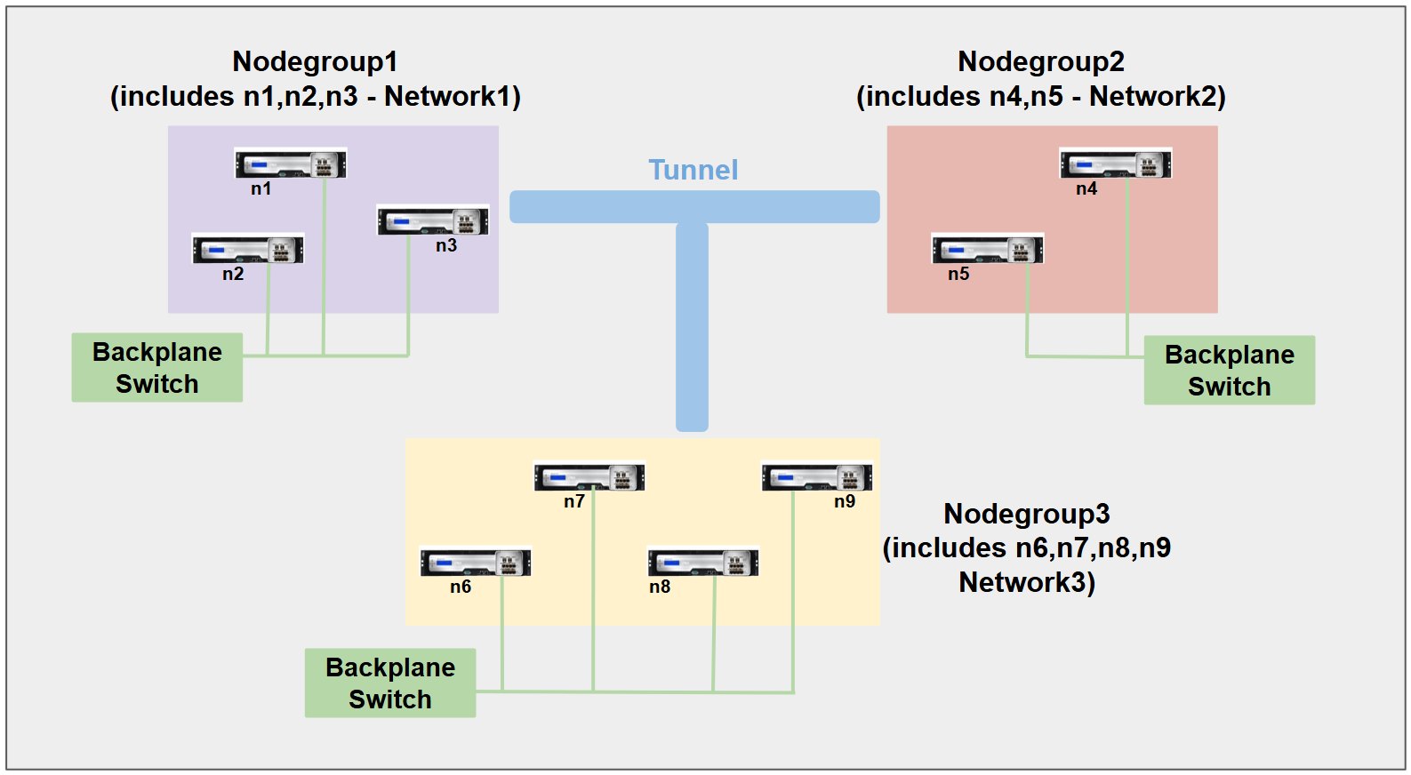
Consider an example of an L3 cluster deployment consisting of the following:
-
Three NetScaler appliances (n1, n2, and n3) nodes are grouped into Nodegroup1.
-
Similarly, the nodes n4 and n5 are grouped in Nodegroup2. In the third network, there are four nodes: n6, n7, n8, and n9.
-
The NetScaler appliances that belong to the same network are combined to form a node group.
Points to consider before configuring the L3 cluster
Consider the following points before configuring the L3 cluster on a NetScaler appliance:
-
The backplane is not mandatory while configuring L3 subnets. If the backplane is not specified, the node does not go to the backplane fail state.Note:If you have more than one node in the same L2 network, it is mandatory to define the backplane interface. If the backplane interface is not mentioned, the nodes go to the backplane fail state.
-
L2 features and striped SNIPs are not supported in the L3 cluster.
-
The external traffic distribution in the L3 cluster supports only Equal Cost Multiple Path (ECMP).
-
The ICMP errors and fragmentation are not processed when steering is disabled in an L3 cluster deployment:
-
The networking entities (
route, route6, pbr, andpbr6) must be bound to the configuration node group. -
VLAN, RNAT, and IP tunnel cannot be bound to a configuration node group.
-
Configuration node group must always have property STRICT “YES.
-
The cluster nodes must not be added to a config node group using the
add cluster nodecommand. -
The
add cluster instance -INC enabledcommand clears the networking entities (route, route6, PBR, pb6, RNAT, IP tunnel, ip6tunnel). -
The
clear config extended+command does not clear the entities (route, route6, PBR, pb6, RNAT, IP tunnel, ip6tunnel) in an L3 cluster.
Configuring the L3 cluster
In an L3 cluster configuration, the cluster command has different attributes to configure that is based on nodes, and node groups. The L3 cluster configuration also includes an IPv6 profile apart from IPv4 profiles.
Configuring an L3 cluster on a NetScaler appliance consists of the following tasks:
-
Create a cluster instance
-
Create a node group in L3 cluster
-
Add a NetScaler appliance to the cluster and group with node group
-
Add the cluster IP address to the node
-
Enable the cluster instance
-
Save the configuration
-
Add a node to an existing node group
-
Create a node group in L3 cluster
-
Group new nodes to the newly created node group
-
Join the node to the cluster
Configuring the following by using the CLI
-
To create a cluster instance
add cluster instance <clid> -inc <ENABLED|DISABLED> -processLocal <ENABLED|DISABLED>Note:The “inc” parameter must be ENABLED for an L3 cluster. -
To create a nodegroup in L3 cluster
add cluster nodegroup <name> -
To add a NetScaler appliance to the cluster and to associate with nodegroup
add cluster node <nodeid> <nodeip> -backplane <interface_name> nodegroup <ng> –tunnelmode UDP -
To add the cluster IP address on this node
add ns ip <IPAddress> <netmask> -type clip -
Enable the cluster instance
enable cluster instance <clId> -
Save the configuration
save ns config -
Warm reboot the appliance
reboot -warm -
To add a new node to an existing nodegroup
add cluster node <nodeid> <nodeip> -nodegroup <ng> –tunnelmode UDP -
To create a new nodegroup in L3 cluster
add cluster nodegroup <ng> -
To group new nodes to the newly created nodegroup
add cluster node <nodeid> <nodeip> -nodegroup <ng> –tunnelmode UDP -
To join the node to the cluster
join cluster –clip <ip_addr> -password <password>
Example: The following is an example configuration for nodegroup1 and nodegroup2.

     > add cluster instance 1 –inc ENABLED –processLocal ENABLED

        Done

     > add cluster nodegroup ng1

        Done

     > add cluster node 0 1.1.1.1 –state ACTIVE -backplane 0/1/1 –nodegroup ng1 –tunnelmode UDP

        Done

     > add ns ip 1.1.1.100 255.255.255.255 –type clip

        Done

     > enable cluster instance 1

        Done

     > save ns config

        Done

     > add cluster node 1 1.1.1.2 –state ACTIVE –nodegroup ng1 –tunnelmode UDP

        Done

     > add cluster nodegroup ng2

        Done

     > add cluster node 4 2.2.2.1 –state ACTIVE –nodegroup ng2 –tunnelmode UDP

        Done

     > add cluster node 5 2.2.2.2 –state ACTIVE –nodegroup ng2 –tunnelmode UDP

        Done

     > join cluster -clip 1.1.1.100 -password nsroot
Advertising cluster IP address of a L3 cluster
Configure the cluster IP address to be advertised to the upstream router to make the cluster configuration accessible from any subnet. The cluster IP address is advertised as a kernel route by the dynamic routing protocols configured on a node.
Advertising the cluster IP address consists of the following tasks:
-
Enable the host route option of the cluster IP address. The host route option pushes the cluster IP address to a ZebOS routing table for kernel route redistribution through dynamic routing protocols.
-
Configuring a dynamic routing protocol on a node. A dynamic routing protocol advertises the cluster IP address to the upstream router. For more information on configuring a dynamic routing protocol, see Configuring Dynamic Routes.
To enable the host route option of the cluster IP address by using the CLI
At the command prompt, type:
-
add nsip <IPAddress> <netmask> -hostRoute ENABLED -
show nsip <IPAddress>
    > add ns ip 10.102.29.60 255.255.255.255 -hostRoute ENABLED

     > Done
Spotted, partially striped configurations on L3 cluster
The spotted and partially striped configurations on the L3 cluster slightly differ from the L2 cluster. The configuration might differ from node to node as the nodes reside on different subnets. The network configurations can be node specific in the L3 cluster, hence you have to configure the spotted or partially striped configurations based on the below-mentioned parameters.
To configure spotted, partially striped configurations on a NetScaler appliance over the L3 cluster, perform the following tasks:
-
Add a cluster owner group to an IPv4 static routing table
-
Add a cluster owner group to an IPv6 static routing table
-
Add a cluster owner group to an IPv4 policy-based routing (PBR)
-
Add a cluster owner group to an IPv6 PBR
-
Add a VLAN
-
Bind a VLAN to a specific owner group of cluster node group
Configuring the following by using the CLI
-
To add a cluster ownergroup to an IPv4 static route table of the NetScaler appliance
add route <network> <netmask> <gateway> -owner group <ng> -
To add a cluster ownergroup to an IPv6 static route table of the NetScaler appliance
add route6 <network> -owner group <ng> -
To add a cluster ownergroup to an IPv4 PBR
add pbr <name> <action> -owner group <ng> -
To add a cluster ownergroup to an IPv6 PBR
add pbr6 <name> <action> -owner group <ng> -
To add a VLAN
add vlan <id> -
To bind a VLAN to a specific ownergroup of cluster nodegroup
bind vlan <id> -ifnum – [IPAddress <ipv4_addr | ipv6_addr> [-owner group <ng>]The following commands are sample examples of spotted and partially striped configurations, which can be configured by using the CLI.
    > add route 10.102.29.0 255.255.255.0 10.102.29.2 –ownergroup ng2

         Done

     > add route6 fe80::9404:60ff:fedd:a464/64 –ownergroup ng1

         Done

     > add pbr pbr1 allow –ownergroup ng1

         Done

     > add pbr6 pbr2 allow –ownergroup ng2

         Done

     > add vlan 2

         Done

     > bind vlan 2 –ifnum 1/2 –[IPAddress 10.102.29.80 | fe80::9404:60ff:fedd:a464/64-ownergroup ng1

         Done
Configure node group
In an L3 cluster, to replicate the same set of configurations on more than one node group, the following commands are used:
Configuring the following by using the CLI
-
To add an IPv4 static route to the routing table of the NetScaler appliance
add route <network> <netmask> <gateway> -ownerGroup <ng>
Sample Configuration:
add route 0 0 10.102.53.1 –ownerGroup ng1

 add route 0 0 10.102.53.1 –ownerGroup ng2
You define a new node group 'all' to support the preceding configuration, and have to configure the following commands:
Configuring the following by using the CLI
-
To add a new nodegroup to cluster with strict parameter
add cluster node group <name> -strict <YES | NO> -
To bind a cluster node or an entity to the given nodegroup
bind cluster nodegroup <name> -node <nodeid> -
To add IPv4 static route to all ownergroup
add route <network> <netmask> <gateway> -ownerGroup <ng>
Sample configuration:
add cluster nodegroup all –strict YES

 bind cluster nodegroup all –node 1

 bind cluster nodegroup all –node 2

 add route 0 0 10.102.53.1 –ownerGroup all
Traffic distribution in a L3 cluster
In a cluster setup, external networks view the collection of NetScaler appliances as a single entity. So, the cluster must select a single node that must receive the traffic. In the L3 cluster this selection is done using the ECMP. The selected node is called the flow receiver.
Note
For an L3 cluster (nodes across different networks), only the ECMP traffic distribution can be used.
The flow receiver gets the traffic and then, using internal cluster logic determines the node that must process the traffic. This node is called the flow processor. The flow receiver steers the traffic to the flow processor over the backplane if the flow receiver and the flow processor are on the same network. The traffic is steered through the tunnel if the flow receiver and the flow processor are on different networks.
Note
-
The flow receiver and flow processor must be nodes capable of serving traffic.
-
From NetScaler 11 onwards, you can disable steering on the cluster backplane. For more information, see Disabling steering on the cluster backplane.

The preceding figure shows a client request flowing through the cluster. The client sends a request to a virtual IP (VIP) address. A traffic distribution mechanism configured on the client data plane selects one of the cluster nodes as the flow receiver. The flow receiver receives the traffic, determines the node that must process the traffic, and steers the request to that node (unless the flow receiver selects itself as the flow processor). If the flow processor and flow receiver are in the same node group, the packet is steered over the backplane. And if the flow processor and flow receiver are in different node groups, then the packet is steered through the tunnel over the routed path.
The flow processor establishes a connection with the server. The server processes the request and sends the response to the subnet IP (SNIP) address that sent the request to the server. Since in the L3 cluster the SNIP is always a spotted SNIP, the node that owns the SNIP address receives the response from the server.