
Setting up inter-node communication
The nodes in a cluster setup communicate with one another using the following inter-node communication mechanisms:
-
Nodes that are within the network (the same subnet) communicate with each other through the cluster backplane. The backplane must be explicitly set up. The following are the detailed steps.
-
Across networks, steering of packets is done through a GRE tunnel and other node-to-node communication is routed across nodes as required.
Important
-
From Release 11.0 all builds, a cluster can include nodes from different networks.
-
From Release 13.0 build 58.3, GRE steering is supported on Fortville NICs in an L3 cluster.
To set up the cluster backplane, do the following for every node
-
Identify the network interface that you want to use for the backplane.
-
Connect an Ethernet or optical cable from the selected network interface to the cluster backplane switch.
For example, to use interface 1/2 as the backplane interface for node 4, connect a cable from the 1/2 interface of node 4 to the backplane switch.
Important points to note when setting up the cluster backplane
-
Do not use the appliance's management interface (0/x) as the backplane interface. In a cluster, the interface 0/1/x is read as:0 -> node ID 0 1/x -> NetScaler interface
-
Use a proper network topology to prevent any loops on the backplane interface. Ensure that the MAC address of the peer node's backplane interface is correctly resolved to the local node's backplane interface.
-
Do not use the backplane interfaces for the client or server data planes.
-
Citrix® recommends using the link aggregate (LA) channel for the cluster backplane.Note:After you unbind an interface from the LA channel, ensure that you set an appropriate MTU size for the unbound interface.
-
In a two-node cluster, where the backplane is connected back-to-back, the cluster is operationally DOWN under any of the following conditions:
-
One of the nodes is rebooted.
-
The backplane interface of one of the nodes is disabled.
Therefore, Citrix recommends that you dedicate a separate switch for the backplane, so that the other cluster node and traffic are not impacted. You cannot scale out the cluster with a back-to-back link. You might encounter a downtime in the production environment when you scale out the cluster nodes. -
-
Backplane interfaces of all nodes of a cluster must be connected to the same switch and bound to the same L2 VLAN.
-
If you have multiple clusters with the same cluster instance ID, make sure that the backplane interfaces of each cluster are bound to a different VLAN.
-
The backplane interface is always monitored, regardless of the HA monitoring settings of that interface.
-
The state of MAC spoofing on the different virtualization platforms can affect the steering mechanism on the cluster backplane. Therefore, make sure that the appropriate state is configured:
-
XenServer® - Disable MAC spoofing
-
Hyper-V - Enable MAC spoofing
-
VMware ESX - Enable MAC spoofing (also make sure "Forged Transmits" is enabled)
-
-
The Maximum Transmission Unit (MTU) value for the cluster backplane is automatically updated. However, if jumbo frames are configured on the cluster, the MTU of the cluster backplane must be explicitly configured.The configured MTU value must be the same across all nodes in the cluster for the following:
-  Server data plane (X)
 -  Client data plane (Y)
- Backplane: The configured MTU value must be set to 78 + maximum of X and Y.Note:The MTU values for the server data plane (X) and client data plane (Y) do not need to be the same.For example, if the MTU of a server data plane is 7500 and of the client data plane is 8922 across the cluster, then the MTU of a cluster backplane must be set to 78 + 8922 = 9000 across the cluster.To set this MTU, use the following command:> set interface <backplane_interface> -mtu <value> -
The MTU for the interfaces of the backplane switch must be specified to be greater than or equal to 1,578 bytes. This requirement is applicable for the following:
-
All Layer 2 clusters.
-
Only within the node group for Layer 3 clusters.
-
The cluster that supports features like MBF, L2 policies, ACLs, CLAG routing, and vPath.
Note:The default MTU size for a backplane interface is 1578. To reset the MTU size to the default value, you must use theunset interface <backplane_interface> -mtucommand. -
UDP based tunnel support for L2 and L3 cluster
Starting from NetScaler release 13.0 build 36.x, NetScaler L2 and L3 cluster can steer the traffic using UDP based tunneling. It is defined for the inter-node communications of two nodes in a cluster. By using the “tunnel mode” parameter, you can set GRE or UDP tunnel mode from the add and set cluster node command.
In an L3 cluster deployment, packets between NetScaler nodes are exchanged over an unencrypted GRE tunnel that uses the NSIP addresses of the source and destination nodes for routing. When this exchange occurs over the internet, in the absence of an IPsec tunnel, the NSIPs are exposed on the internet, and might result in security issues.
Important
Citrix recommends customers to establish their own IPsec solution when using a L3 cluster.
The following table helps you to categorize the tunnel support based on different deployments.
| Steering Types | AWS | Microsoft Azure | On -premises |
|---|---|---|---|
| MAC | Not supported | Not supported | Supported |
| GRE tunnel | Supported | Not supported | Supported |
| UDP tunnel | Supported | Supported | Supported |
Important
In a L3 cluster, the tunnel mode is set to GRE by default.
Configuring a UDP based tunnel
You can add a cluster node by setting the parameters of node ID and mention the state. Configure the backplane by providing the interface name, and select the tunnel mode of your choice (GRE or UDP).
Note:
You must configure the tunnel mode from the Cluster IP address.
CLI procedures
To enable the UDP tunnel mode by using the CLI.
At the command prompt, type:
-
add cluster node <nodeId>@ [-state <state>] [-backplane <interface_name>] [-tunnelmode <tunnelmode>] -
set cluster node <nodeId>@ [-state <state>] [-tunnelmode <tunnelmode>]
Note
Possible values for tunnel mode are NONE, GRE, UDP.
Example
-
add cluster node 1 –state ACTIVE –backplane 1/1/1 -tunnelmode UDP -
set cluster node 1 –state ACTIVE –tunnelmode UDP
GUI procedures
To enable the UDP tunnel mode by using the GUI.
-
Navigate to System > Cluster > Nodes.
-
In the Cluster Nodes page, click Add.
-
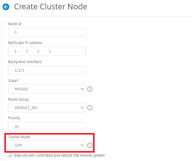
In the Create Cluster Node, set the Tunnel Mode parameter to UDP and click Create.
-
Click Close.