Field replaceable units
NetScaler field replaceable units (FRU) are ADC components that a user or a technician can replace at the user’s site. The FRUs for a NetScaler appliance include DC or AC power supplies, solid-state (SSD) or hard-disk drives (HDD), direct attach cable (DAC), the bezel of the appliance, transceivers, and rail kits.
Notes:
The SSD or HDD stores your configuration information, and it must be restored from a backup after the unit is replaced.
All NetScaler FRUs must be purchased from Citrix. Components not provided by NetScaler are not supported on NetScaler appliances. Contact your NetScaler sales representative to buy FRUs for your appliance.
Power supply
For appliances containing two power supplies, the second power supply is optional but recommended. Some appliances can accommodate four power supplies, and require two power supplies as a bare minimum for proper operation. As a best practice, plug in all the power supplies for redundancy.
The appliance ships with a standard power cord that plugs into the appliance’s power supply. It has a NEMA 5–15 plug on the other end for connecting to the power outlet on the rack or in the wall.
For power-supply specifications, see Common Components.
Note:
If you suspect that a power-supply fan is not working, see the description of your platform. On some platforms, what appears to be the fan does not turn, and the actual fan turns only when necessary.
On each power supply, a bicolor LED indicator shows the condition of the power supply.
Electrical safety precautions for power supply replacement
- Make sure that the appliance has a direct physical connection to earth ground during normal use. When installing or repairing an appliance, always connect the ground circuit first and disconnect it last.
- Never touch a power supply when the power cord is plugged in. As long as the power cord is plugged in, line voltages are present in the power supply even if the power switch is turned off.
For the complete list of safety precautions, see Safety, Cautions, Warnings, and Other Information.
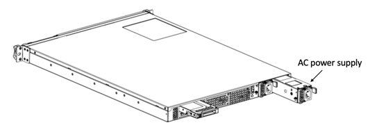
Replace an AC power supply
Most NetScaler MPX platforms accommodate two power supplies. Some platforms accommodate four power supplies. All NetScaler appliances function properly with a single power supply, except the appliances that accommodate four power supplies. These appliances need two power supplies for proper operation. The other power supply serves as a backup. All power supplies must be of the same type (AC or DC).
Note:
If the appliance has only one power supply, you have to shut down the appliance before replacing the power supply. With two power supplies, you can replace one power supply without shutting down the appliance, provided the other power supply is working. With four power supplies, you can replace one or two power supplies without shutting down the appliance, provided the other two power supplies are working.
To install or replace an AC power supply on a NetScaler appliance:
-
Align the handle perpendicular to the power supply. Loosen the thumbscrew (if it is screwed) and press the lever toward the handle and pull out the existing power supply.
Note
The illustration in the following figures might not represent the actual NetScaler appliance.
Figure 1. Remove the existing AC power supply
- Carefully remove the new power supply from its box.
- On the back of the appliance, align the power supply with the power supply slot.
-
Insert the power supply into the slot and press against the semicircular handle until you hear the power supply snap into place.
- Connect the power supply to a power source. If connecting all power supplies, plug separate power cords into the power supplies and connect them to separate wall sockets.
Note:
NetScaler appliances emit a high-pitched alert in the following scenarios:
- One power supply fails
- You connect only one power cable to an appliance in which two power supplies are installed.
To silence the alarm, press the small red button on the back panel of the appliance. The Disable alarm button is functional only when the appliance has two power supplies.
Replace a DC power supply
Most NetScaler MPX platforms can accommodate two power supplies. Some platforms can accommodate four power supplies. All NetScaler appliances function properly with a single power supply, except the appliances that can accommodate four power supplies. These appliances need two power supplies for proper operation. The other power supply serves as a backup. All power supplies must be of the same type (AC or DC).
Note:
If the appliance has only one power supply, you have to shut down the appliance before replacing the power supply. With two power supplies, you can replace one power supply without shutting down the appliance, provided the other power supply is working. With four power supplies, you can replace one or two power supplies without shutting down the appliance, provided the other two power supplies are working.
To install or replace a DC power supply on a NetScaler appliance:
-
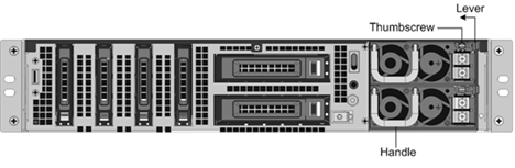
Loosen the thumbscrew and press the lever towards the handle and pull out the existing power supply, as shown in the following figure.
Note:
The illustration in the following figures might not represent the actual NetScaler appliance.
Figure 2. Remove the existing DC power supply
- Carefully remove the new power supply from its box.
- On the back of the appliance, align the power supply with the power supply slot.
-
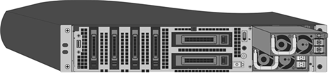
Insert the power supply into the slot while pressing the lever towards the handle. Apply firm pressure to insert the power supply firmly into the slot.
Figure 3. Inserting the Replacement DC Power Supply
- When the power supply is inserted into its slot, release the lever.
- Connect the power supply to a power source. If connecting all power supplies, plug separate power cords into the power supplies and connect them to separate wall sockets.
Note:
NetScaler appliances emit a high-pitched alert in the following scenarios:
- One power supply fails
- You connect only one power cable to an appliance in which two power supplies are installed.
To silence the alarm, press the small red button on the back panel of the appliance. The Disable alarm button is functional only when the appliance has two power supplies.
Solid-state drive
An SSD is a high-performance device that stores data in solid-state flash memory. The MPX SSDs contain the boot loader configuration file, configuration file (ns.conf), licenses, and for some models, the NetScaler software and the user data.
All MPX platforms store the NetScaler software on the SSD. The SSD is mounted as /flash.
Replace a RAID-supported SSD by using the CLI
Note:
The following models support RAID if they have more than one SSD:
- MPX 14000
- MPX 15000
- MPX 16000
- MPX 25000
- MPX 26000
In the NetScaler GUI, navigate to Configuration > System > Diagnostic > Utility > Command line interface. You can also access the CLI from the serial console port or the management port (0/1 or 0/2).
Note:
The RAID status can take READY or DEGRADED values. The drive status can take ONLINE or MISSING values.
To check the status of your SSDs in RAID, at the CLI type:
Command:
sh raid
<!--NeedCopy-->
Output:
RAID1 status: READY
Drive:
       1   ONLINE
       2   ONLINE
Done
<!--NeedCopy-->
If both the SSDs’ show ONLINE and the RAID status shows READY, no action is required.
In the following table, the values in the first column show the drive number on the back panel of the appliance. The drive number in the other columns refers to the number that must be used in the command or as it appears in the output of the CLI and shell.
| Chassis | CLI command | Shell command | Shell command | Shell command |
|---|---|---|---|---|
| Slot in chassis | sh raid |
atacontrol status ar0 |
atacontrol detach / atacontrol attach
|
atacontrol addspare ar0 |
| SSD 1 | drive 1 | drive 0 | ata2 | ad4 |
| SSD 2 | drive 2 | drive 1 | ata3 | ad6 |
The following output indicates SSD 2 has failed and must be replaced.
Command:
sh raid
<!--NeedCopy-->
Output:
RAID1 status: DEGRADED
Drive:
       1   ONLINE
       2   MISSING
Done
<!--NeedCopy-->
Sometimes, the failed drive/SSD might not be reported.
Command:
sh raid
<!--NeedCopy-->
Output:
RAID1 status: DEGRADED
Drive:
       1   ONLINE
Done
<!--NeedCopy-->
From the shell, confirm that drive 1/SSD 2 has failed, RAID status reports DEGRADED and drive 1/SSD 2 reports MISSING, or not present in the output.
-
At the NetScaler command prompt, switch to the shell prompt. Type:
shell -
Check the status of the RAID array. SSD2 shows missing or is not present in the output.
Command:
root@ns# atacontrol status ar0
<!--NeedCopy-->
Output:
ar0: ATA RAID1 status: DEGRADED
subdisks:
       0 ad4  ONLINE
       1 ----  MISSING
<!--NeedCopy-->
OR
ar0: ATA RAID1 status: DEGRADED
subdisks:
       0 ad4  ONLINE
<!--NeedCopy-->
Note:
Drive numbering changes in the shell: SSD 1 reports as drive 0 and SSD 2 as drive 1.
Perform the following steps to restore the RAID array to health by using the atacontrol utility.
-
Detach a failed drive. The failed drive is replaced with a new FRU drive.
-
Attach the FRU drive.
-
Add the FRU drive to the RAID array.
-
Verify that the replacement drive is recognized.
-
Start the rebuild process.
-
Monitor the rebuild process.
-
Verify that the rebuild is successful.
-
Exit the bash shell and verify from the NetScaler CLI.
Example when SSD 2 fails
In the following example, SSD 2/drive 1/ata3 has failed.
-
Detach a failed drive.
root@ns# atacontrol detach ata3 <!--NeedCopy--> -
Physically, remove SSD 2/drive 1 and replace it with a new FRU drive in slot 2.
-
Attach the FRU drive.
root@ns# atacontrol attach ata3 <!--NeedCopy--> -
Add the FRU drive to the RAID array.
root@ns# atacontrol addspare ar0 ad6 <!--NeedCopy--> -
Verify that the replacement drive is recognized.
root@ns# atacontrol status ar0
<!--NeedCopy-->
Output:
ar0: ATA RAID1 status: DEGRADED subdisks: 0 ad4 ONLINE 1 ad6 SPARE <!--NeedCopy--> -
Start the rebuild process.
root@ns# atacontrol rebuild ar0 <!--NeedCopy--> -
Monitor the rebuild process.
root@ns# atacontrol status ar0
<!--NeedCopy-->
Output:
ar0: ATA RAID1 status: REBUILDING 10% completed
subdisks:
   0 ad4  ONLINE
   1 ad6  SPARE
<!--NeedCopy-->
Note:
Rebuilding the RAID array takes some time.
-
Verify that the REBUILD is successful.
root@ns# atacontrol status ar0
<!--NeedCopy-->
Output:
ar0: ATA RAID1 status: READY
subdisks:
   0 ad4  ONLINE
   1 ad6  ONLINE
<!--NeedCopy-->
Note:
After the rebuild operation completes, the subdisks status shows ONLINE, and the RAID status shows READY.
-
Exit the shell and verify the status of the RAID array from the NetScaler CLI.
root@ns# exit
>sh raid
<!--NeedCopy-->
Output:
RAID1 status: READY
Drive:
        1   ONLINE
        2   ONLINE
Done
<!--NeedCopy-->
Example when SSD 1 fails
In the following example, SSD 1/drive 0/ata2 has failed.
-
Detach a failed drive.
root@ns# atacontrol detach ata2 <!--NeedCopy--> -
Physically, remove SSD 1/drive 0 and replace it with a new FRU drive in slot 1.
-
Attach the FRU drive.
root@ns# atacontrol attach ata2 <!--NeedCopy--> -
Add the FRU drive to the RAID array.
root@ns# atacontrol addspare ar0 ad4 <!--NeedCopy--> -
Verify that the replacement drive is recognized.
root@ns# atacontrol status ar0
<!--NeedCopy-->
Output:
ar0: ATA RAID1 status: DEGRADED subdisks: 0 ad4 SPARE 1 ad6 ONLINE <!--NeedCopy--> -
Start the rebuild process.
root@ns# atacontrol rebuild ar0 <!--NeedCopy--> -
Monitor the rebuild process.
root@ns# atacontrol status ar0
<!--NeedCopy-->
Output:
ar0: ATA RAID1 status: REBUILDING 10% completed
subdisks:
   0 ad4  SPARE
   1 ad6  ONLINE
<!--NeedCopy-->
Note:
Rebuilding the RAID array takes some time.
-
Verify that the REBUILD is successful.
root@ns# atacontrol status ar0
<!--NeedCopy-->
Output:
ar0: ATA RAID1 status: READY
subdisks:
   0 ad4  ONLINE
   1 ad6  ONLINE
<!--NeedCopy-->
Note:
After the rebuild operation completes, the subdisks status shows ONLINE, and the RAID status shows READY.
-
Exit the shell and verify the status of the RAID array from the NetScaler CLI.
root@ns# exit
>sh raid
<!--NeedCopy-->
Output:
RAID1 status: READY
Drive:
1   ONLINE
2   ONLINE
Done
<!--NeedCopy-->
Replace a solid-state drive
Replacement SSDs contain a pre-installed version of the NetScaler software and a generic configuration file (ns.conf). However, it does not contain SSL-related certificates and keys, or custom boot settings. Configuration files and customized settings must be restored to a replacement drive from a backup storage location at the customer site, if available. The files to be restored might include:
- /flash/nsconfig/ns.conf: The current configuration file.
- /flash/nsconfig/ZebOS.conf: The ZebOS configuration file.
- /flash/nsconfig/license: The licenses for the NetScaler features.
- /flash/nsconfig/ssl: The SSL certificates and keys required for encrypting data to clients or to back-end servers.
- /nsconfig/rc.netscaler: Customer-specific boot operations (optional).
To replace a solid-state drive:
-
At the NetScaler command prompt, exit to the shell prompt. Type:
shell -
Shut down the NetScaler appliance by typing the following command at the shell prompt:
shutdown –p now -
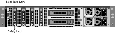
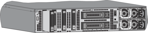
Locate the SSD on the back panel of the appliance. Push the safety latch of the drive cover to the right or down, depending on the platform, while pulling out on the drive handle to disengage. Pull out the faulty drive.
Note:
The illustration in the following figures might not represent the actual NetScaler appliance.
Figure 4. Remove the existing solid-state drive
-
Verify that the replacement SSD is the correct type for the platform.
-
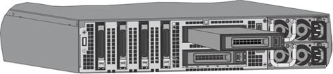
Pick up the new SSD, open the drive handle fully to the left or up, and insert the drive into the slot as far as possible. To seat the drive, close the handle flush with the rear of the appliance so that the drive locks securely into the slot.
Important: When you insert the drive, make sure that the NetScaler® product label is at the top if the drive is inserted horizontally. The label must be at the right if the drive is inserted vertically.
Figure 5. Insert the replacement solid-state drive
-
Turn on the NetScaler appliance. When the appliance starts, it no longer has the previous working configuration. Therefore, the appliance is reachable only through the default IP address of 192.168.100.1/16, or through the console port.
-
Perform the initial configuration of the appliance, as described in Initial Configuration. Log on to the default IP address by using a web browser, or connect to the serial console by using a console cable, to perform the initial configuration.
-
Upload a platform license and any optional feature licenses, including universal licenses, to the NetScaler appliance. For more information, see Licensing.
-
Once the correct NetScaler software version is loaded, you can restore the working configuration. Copy a previous version of the ns.conf file to the
/nsconfigdirectory by using an SCP utility. Alternately, paste the previous configuration into the/nsconfig/ns.conffile from the NetScaler command prompt. To load the newns.conffile, you must restart the NetScaler appliance by entering the reboot command at the NetScaler command prompt.
Hard disk drive
A hard disk drive (HDD) stores logs and other data files. Files stored on the HDD include the newnslog files, dmesg and messages files, and any core/crash files. The HDD comes in various capacities, depending on the NetScaler platform. Hard drives are used for storing files required at runtime. An HDD is mounted as /var.
Replace a hard disk drive
A hard disk drive (HDD) stores log files and other user files. Collection of new log files begins upon boot-up with the new HDD.
To install a hard disk drive:
-
At the NetScaler command prompt, exit to the shell prompt. Type:
shell -
Shut down the NetScaler appliance by typing one of the following commands at the shell prompt.
-
On an MPX appliance, type:
shutdown –p now -
On a non-MPX appliance, type:
shutdown
-
-
Locate the hard disk drive on the back panel of the appliance.
-
Verify that the replacement hard disk drive is the correct type for the NetScaler platform.
-
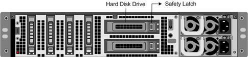
Disengage the hard disk drive by pushing the safety latch of the drive cover to the right or down, depending on the platform, while pulling out on the drive handle. Pull out the faulty drive.
Note:
The illustration in the following figures might not represent the actual NetScaler appliance.
Figure 6. Removing the existing hard disk drive
-
Pick up the new disk drive, open the drive handle fully to the left, and insert the new drive into the slot as far as possible. To seat the drive, close the handle flush with the rear of the appliance so that the hard drive locks securely into the slot.
Important:
When you insert the drive, make sure that the NetScaler product label is at the top.
Figure 7. Insert the replacement hard disk drive
-
Turn on the NetScaler appliance. The appliance starts the NetScaler software and reads the configuration file from the CompactFlash card.
Direct attach cable
A direct attach cable (DAC) assembly is a high performance integrated duplex data link for bi-directional communication. The cable is compliant with the IPF MSA (SFF-8432) for mechanical form factor and SFP+ MSA for direct attach cables. The cable, which can be up to 5 meters long, is data-rate agnostic. Supporting speeds more than 10 Gbps, it is a cost-effective alternative to optical links (SFP+ transceivers and fiber optic cables.)
The transceiver with DAC is hot-swappable. You can insert and remove the transceiver with the attached cable without shutting down the appliance. The NetScaler appliance supports only a passive DAC.
Important:
- DAC is supported only on 10G ports. Do not insert a DAC into a 1G port.
- Do not attempt to unplug the integrated copper cable from the transceiver and insert a fiber cable into the transceiver.
Install a direct attach cable
Note:
The illustrations in the following figures are only for reference and might not represent the actual NetScaler appliance.
To install or remove a direct attach cable:
-
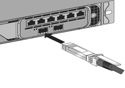
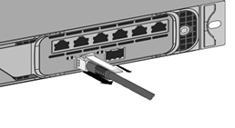
To install the DAC, slide it into the 10G port on the appliance, as shown in the following figure. You hear a click when the DAC properly fits into the port.
Figure 8. Insert a DAC into the 10G port
-
To remove the DAC, pull the tab on the top of the DAC, and then pull the DAC out of the port, as shown in the following figure.
Figure 9. Remove a DAC from the 10G port
Bezel
The bezel of a NetScaler appliance is now available as a FRU and can be replaced in the field.
Note:
The bezel FRU is supported only on the MPX/SDX 9100 platform.
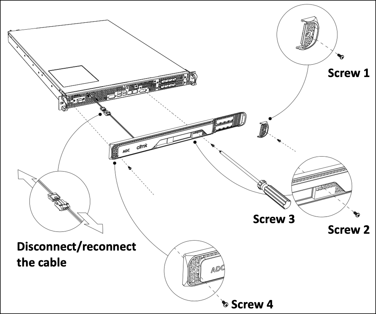
To replace the bezel
- Remove the five screws that attach the bezel to the chassis front.
- Disconnect the cable (see image).
- Discard the old bezel.
- Reconnect the cable to the new bezel.
-
Attach the new bezel to the chassis front using screws.
Figure 1: Replacing the 2U bezel
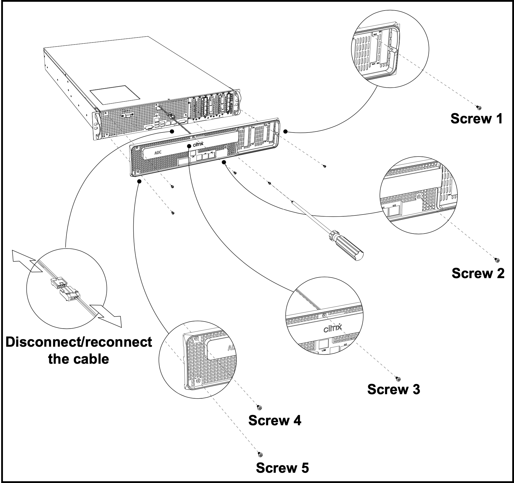
Figure 2: Replacing the 1U bezel
Transceivers
Transceivers, in different speeds, are available as a FRU. Reach out to your NetScaler sales contact or partner to order transceivers.
For information about removing and installing transceivers, see Install and remove 1G SFP transceivers.
Rail kits
Rail kits are available as a FRU. Rail kits are available in 28 inches (38 inches extended) and 23 inches (33 inches extended). Reach out to your NetScaler sales contact or partner to order rail kits.
For information about attaching the rail kits to the appliance, see Rack-mount the appliance.