-
Configuration guide for Citrix Virtual Apps and Desktops™ workloads
-
Citrix SD-WAN Orchestrator™ on-premises configuration on Citrix SD-WAN appliance
-
-
-
-
How to configure IPsec tunnels for virtual and dynamic paths
-
How to configure IPsec tunnel between SD-WAN and third-party devices
-
-
This content has been machine translated dynamically.
Dieser Inhalt ist eine maschinelle Übersetzung, die dynamisch erstellt wurde. (Haftungsausschluss)
Cet article a été traduit automatiquement de manière dynamique. (Clause de non responsabilité)
Este artículo lo ha traducido una máquina de forma dinámica. (Aviso legal)
此内容已经过机器动态翻译。 放弃
このコンテンツは動的に機械翻訳されています。免責事項
이 콘텐츠는 동적으로 기계 번역되었습니다. 책임 부인
Este texto foi traduzido automaticamente. (Aviso legal)
Questo contenuto è stato tradotto dinamicamente con traduzione automatica.(Esclusione di responsabilità))
This article has been machine translated.
Dieser Artikel wurde maschinell übersetzt. (Haftungsausschluss)
Ce article a été traduit automatiquement. (Clause de non responsabilité)
Este artículo ha sido traducido automáticamente. (Aviso legal)
この記事は機械翻訳されています.免責事項
이 기사는 기계 번역되었습니다.책임 부인
Este artigo foi traduzido automaticamente.(Aviso legal)
这篇文章已经过机器翻译.放弃
Questo articolo è stato tradotto automaticamente.(Esclusione di responsabilità))
Translation failed!
How to configure IPsec tunnel between SD-WAN and third-party devices
To configure IPsec tunnel for intranet or LAN service:
-
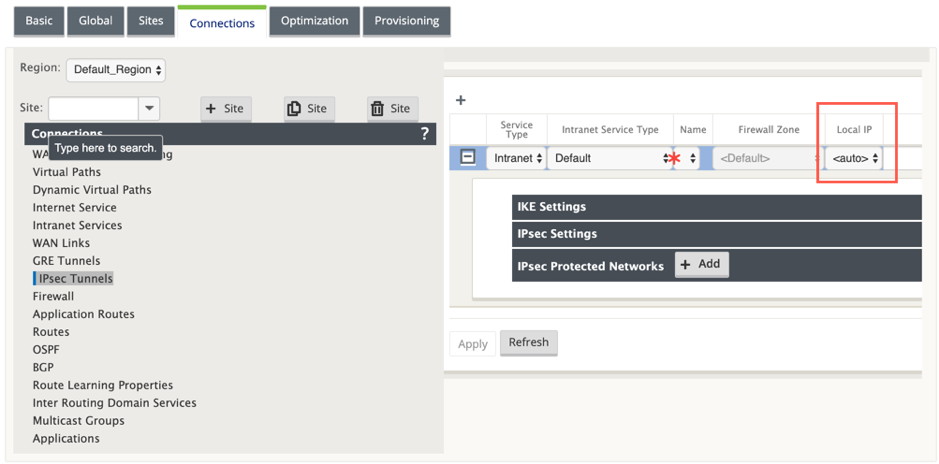
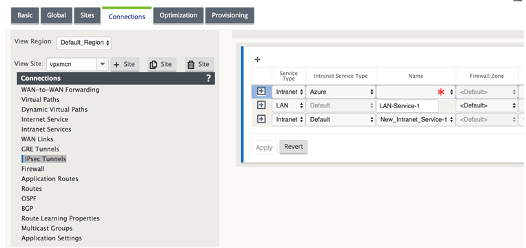
In the Configuration Editor, navigate to Connections > View Site > [Site Name] > IPsec Tunnels. Choose a Service Type (LAN or Intranet).
-
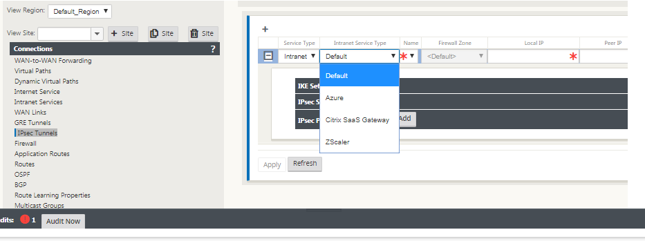
Enter a Name for the service type. For Intranet service type, the configured Intranet Server determines which Local IP addresses are available.
Citrix SD-WAN™ can now establish IPsec tunnels when a WAN link is directly terminated on the appliance and a dynamic IP is being assigned to the WAN link.
With 11.1.0 release, Intranet IPsec tunnels must be configurable when the local tunnel IP address is not or cannot be known. This helps in creating IPsec tunnels on the interfaces whose address is assigned through DHCP.
While configuring the interface for IPsec tunnel, a local tunnel IP must be mentioned. This interface is modified to allow an empty IP to be selected when the tunnel type is Intranet.
Also, the label for an unset address is changed to Auto when the tunnel type is Intranet.
If the Local IP is set as Auto, it has the ability of taking the IP address that is incorporated for the access interface on that WAN link. That WAN link access interface might get the IP either statically configured or from DHCP. IPsec tunnel is established using the primary WAN link access interface by default.
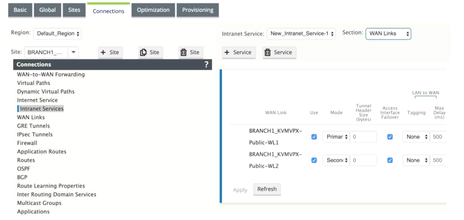
Earlier, you can establish IPsec tunnels over a single WAN link. This exposes the branch environment to service loss during periods of outright link failures and when packet loss on a link is inadvertently high to allow for reliable connectivity.
From 11.1.0 release onwards, you can use two WAN links for establishing IPsec tunnels to guard branch environments against periods of service disruption. If the primary link goes down, the secondary link turns active/up within milliseconds.
Note
When the <Auto> option is selected, the IPsec tunnel is established using the primary WAN link access interface. If the primary wan link goes down IPsec tunnel is established using the secondary WAN link access interface.
-
Select the available Local IP address and enter the Peer IP address of the IPsec tunnel.
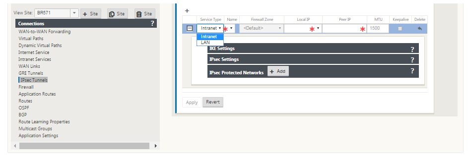
Note
If the Service Type is Intranet, the IP address is pre-determined by the chosen Intranet Service.
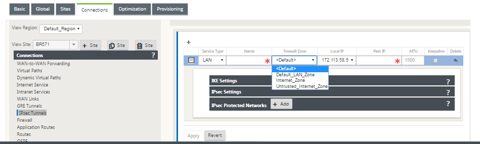
-
Configure IPsec settings by applying the criteria described in the following tables. When finished, click Apply to save your settings.
| Field | Description | Value |
|---|---|---|
| Service Type | Choose a service type from the drop-down menu | Intranet, LAN |
| Name | If the service type is Intranet, choose from the list of configured intranet services in the drop-down menu. If the service type is LAN, enter a unique name | Text string |
| Local IP | Choose the local IP address of the IPsec Tunnel from the drop-down menu of available virtual IP addresses configured at this Site | IP address |
| Peer IP | Enter the peer IP address of the IPsec Tunnel | IP address |
| MTU | Enter the MTU for fragmenting IKE and IPsec fragments | Default: 1500 |
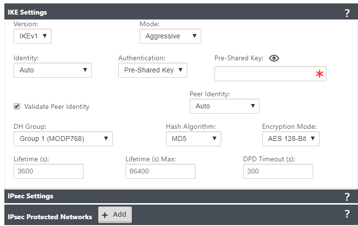
| IKE Settings | Version: Choose an IKE version from the drop-down menu | IKEv1 IKEv2 |
| Mode | Choose a mode from the drop-down menu | FIPS compliant: Main, Non-FIPS compliant: Aggressive |
| Identity | Choose an Identity from the drop-down menu | Auto IP Address Manual IP Address User FQDN |
| Authentication | Choose the authentication type from the drop-down menu | Pre-Shared Key: If you are using a pre-shared key, copy and paste it into this field. Click the Eyeball () icon to view the Pre-Shared Key. Certificate: If you are using an identity certificate, choose it from the drop-down menu. |
| Validate Peer Identity | Select this check box to validate the IKE’s peer. If the peer’s ID type is not supported, do not enable this feature | None |
| DH Group | Choose Diffie-Hellman group to use for IKE key generation from the drop-down menu | Non-FIPS compliant: Group 1, FIPS-compliant: Group 2 Group 5 Group 14 Group 15 Group 16 Group 19 Group 20 Group 21 |
| Hash Algorithm | Choose an algorithm from the drop-down menu to authenticate IKE messages | Non-FIPS compliant: MD5 FIPS compliant: SHA1 SHA-256 |
| Encryption Mode | Choose the Encryption Mode for IKE messages from the drop-down menu | AES 128-bit AES 192-bit AES 256-bit |
| Lifetime (s) | Enter the preferred duration, in seconds, for an IKE security association to exist | 3600 seconds (default) |
| Lifetime (s) Max | Enter the maximum preferred duration, in seconds, to allow an IKE security association to exist | 86400 seconds (default) |
| DPD Timeout (s) | Enter the Dead Peer Detection timeout, in seconds, for VPN connections | 300 seconds (default) |
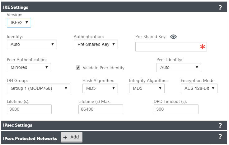
| IKEv2 | Peer Authentication: Choose Peer Authentication from the drop-down menu | Mirrored Pre-Shared Key Certificate |
| IKE2 - Pre-shared key | Peer Pre-Shared Key: Paste the IKEv2 Peer Pre-Shared Key into this field for authentication. Click the eyeball () icon to view the Pre-Shared Key | Text string |
| Integrity Algorithm | Choose an algorithm as the hashing algorithm to use for HMAC verification from the drop-down menu | Non-FIPS compliant: MD5 FIPS compliant: SHA1 SHA-256 |
Note:
If the terminating IPsec router includes Hash-based Message Authentication Code (HMAC) in the config, change the IPsec mode to EXP+Auth with a hashing algorithm as SHA1.
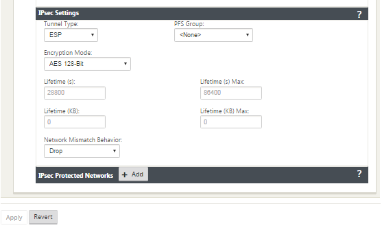
IPsec and IPsec Protected Network Settings:
| Field | Description | Value (s) |
|---|---|---|
| Tunnel Type | Choose the Tunnel Type from the drop-down menu | ESP ESP+Auth ESP+NULL AH |
| PFS Group | Choose Diffie-Hellman group to use for perfect forward secrecy key generation from the drop-down menu | None Group 1 Group 2 Group 5 Group 14 Group 15 Group 16 Group 19 Group 20 Group 21 |
| Encryption Mode | Choose the Encryption Mode for IPsec messages from the drop-down menu | If you chose ESP or ESP+ Auth, select either one of the following, AES 128-Bit, AES 192-Bit, AES 256-Bit, AES 128-Bit GCM 64-Bit, AES 192-Bit GCM 64-Bit, AES 256-Bit GCM 64-Bit, AES 128-Bit GCM 96-Bit, AES 192-Bit GCM 96-Bit, AES 256-Bit GCM 96-Bit, AES 128-Bit GCM 128-Bit, AES 192-Bit GCM 128-Bit, AES 256-Bit GCM 128-Bit. AES 128/192/256-Bit are CBC supported. |
| Lifetime (s) | Enter the amount of time, in seconds to allow an IPsec security association to exist | 28800 seconds (default) |
| Lifetime Max (s) | Enter the maximum amount of time, in seconds to allow an IPsec security association to exist | 86400 seconds (default) |
| Lifetime (KB) | Enter the amount of data, in kilobytes, for an IPsec security association to exist | Kilobytes |
| Lifetime (KB) Max | Enter the maximum amount of data, in kilobytes, to allow an IPsec security association to exist | Kilobytes |
| Network Mismatch Behavior | Choose the action to take if a packet does not match the IPsec Tunnel’s Protected Networks from the drop-down menu | Drop, Send Unencrypted, Use Non-IPsec Route |
| IPsec Protected Networks | Source IP/Prefix: After clicking the Add (+ Add) button, enter the Source IP and Prefix of the network traffic the IPsec Tunnel will protect | IP address |
| IPsec Protected Networks | Destination IP/Prefix: Enter the Destination IP and Prefix of the network traffic the IPsec Tunnel will protect | IP address |
Monitor IPsec Tunnels
Navigate to Monitoring>IKE/IPsec in the SD-WAN appliance GUI to view and monitor IPsec tunnel configuration.
Share
Share
This Preview product documentation is Cloud Software Group Confidential.
You agree to hold this documentation confidential pursuant to the terms of your Cloud Software Group Beta/Tech Preview Agreement.
The development, release and timing of any features or functionality described in the Preview documentation remains at our sole discretion and are subject to change without notice or consultation.
The documentation is for informational purposes only and is not a commitment, promise or legal obligation to deliver any material, code or functionality and should not be relied upon in making Cloud Software Group product purchase decisions.
If you do not agree, select I DO NOT AGREE to exit.