NetScaler SDX 15000-50G
The NetScaler SDX 15020/15030/15040/15060/15080/15100/15120 50G models are 2U appliances. This platform has a dual 8-core processor and 128 GB memory. The SDX 15000-50G appliance provides a total of 12 network ports:
- Eight 10G SFP+ Ethernet Ports
- Four 50G Ethernet Ports
For information about the software releases supported on the NetScaler hardware platforms, see NetScaler SDX Hardware and Component Compatibility Matrix
The illustrations in this guide are only indicative and might not represent the actual NetScaler appliance.
Figure 1. NetScaler SDX 15000-50G, front panel
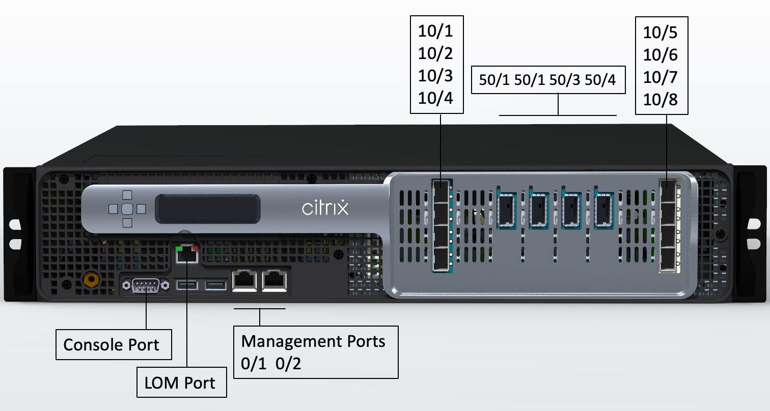
The NetScaler SDX 15000-50G appliance has the following ports:
- One RS232 Serial Console Port.
- One 10/100/1000 Base-T RJ45 copper Ethernet lights out management port. Use this port to remotely monitor and manage the appliance independently of the NetScaler software.
- Two 10/100/1000Base-T RJ45 copper Ethernet Management Ports, numbered 0/1 and 0/2. These ports are used to connect directly to the appliance for NetScaler administration functions.
- Eight 10G SFP+ Ethernet ports, numbered 10/1 to 10/8. Each port has its own LED.
- Four 50G ports, numbered 50/1 to 50/4. Each port has its own LED. For information about supported transceivers per port, see 25G, 40G, 50G, and 100G ports.
Figure 2. NetScaler SDX 15000-50G, rear panel
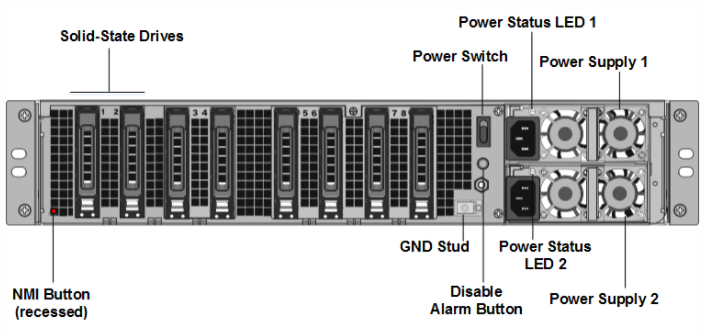
The back panel of the SDX 15000-50G appliance has the following components:
-
Two 240 GB RAID-supported removable boot solid-state drives (SSDs), (slots 1 and 2) as shown in figure 2. Two 240 GB RAID-supported removable storage repositories (slots 3 and 4 paired) SSDs, and four 480 GB storage repositories (slots 5–6 paired and 7–8 paired) SSDs.
Note: Drive densities might increase as components become EOL but its size is never smaller than the original.
-
A power switch, which turns power to the appliance on or off. If the OS is functional, press the switch for less than two seconds to power down the system with a graceful shutdown. If the OS is not responsive, press the power switch for more than 4 seconds to force the power off.
-
Two hot-swappable 100–240 VAC input power supply modules. Each power supply has an LED indicating its status, as shown in the following table.
| LED Color | LED Indicates |
|---|---|
| OFF | No power to any power supply in the appliance. |
| Flashing RED | No power to this power supply module. |
| Flashing GREEN | Power supply is in standby mode. |
| GREEN | Power supply is functional. |
| RED | Power supply failure. |
| Flashing RED and GREEN | Warning (OVP/UVP/OCP/OTP/Fan); OVP = Over Voltage Protection; UVP = Under Voltage Protection; OTP = Over Temperature Protection. |
- A Disable alarm button, which is functional only when the appliance has dual redundant, hot-swappable power supplies. Press this button to silence the power alarm when one of the two power supplies loses input power or when a power supply is malfunctioning.
- A Non-Maskable Interrupt (NMI) button, used at the request of Technical Support to initiate a core dump. To press this red button, which is recessed to prevent unintentional activation, use a pen, pencil, or other pointed object. The NMI Button is also available remotely over the network in the LOM GUI, in the Remote Control menu. For more information about the lights out management port of the appliance, see Lights out management port of the NetScaler SDX appliance.