Improved Path Mapping and Bandwidth Usage
Path mapping and bandwidth usage enhancements are implemented in the Monitoring tab to show traffic flows. For instance, when only one virtual path is serving a network connection, and if that virtual path becomes inactive, a new best path is chosen and the initial path becomes the last best path. This scenario is implemented when demand for bandwidth is less and when only one path is chosen
When more than one virtual path is serving a connection, you notice one current best path and next best path, if available. If only one path exists to process traffic, assuming there are more than two paths processing traffic and the path table is updated with two paths, then the Monitoring tab in SD-WAN GUI for flows will display current best path as first path and the next comma separate path as the last best path. This scenario is implemented when there is a need for more paths with demand for bandwidth.
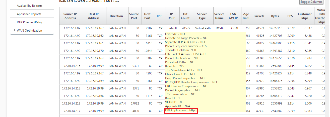
Monitoring DPI application information in SD-WAN GUI
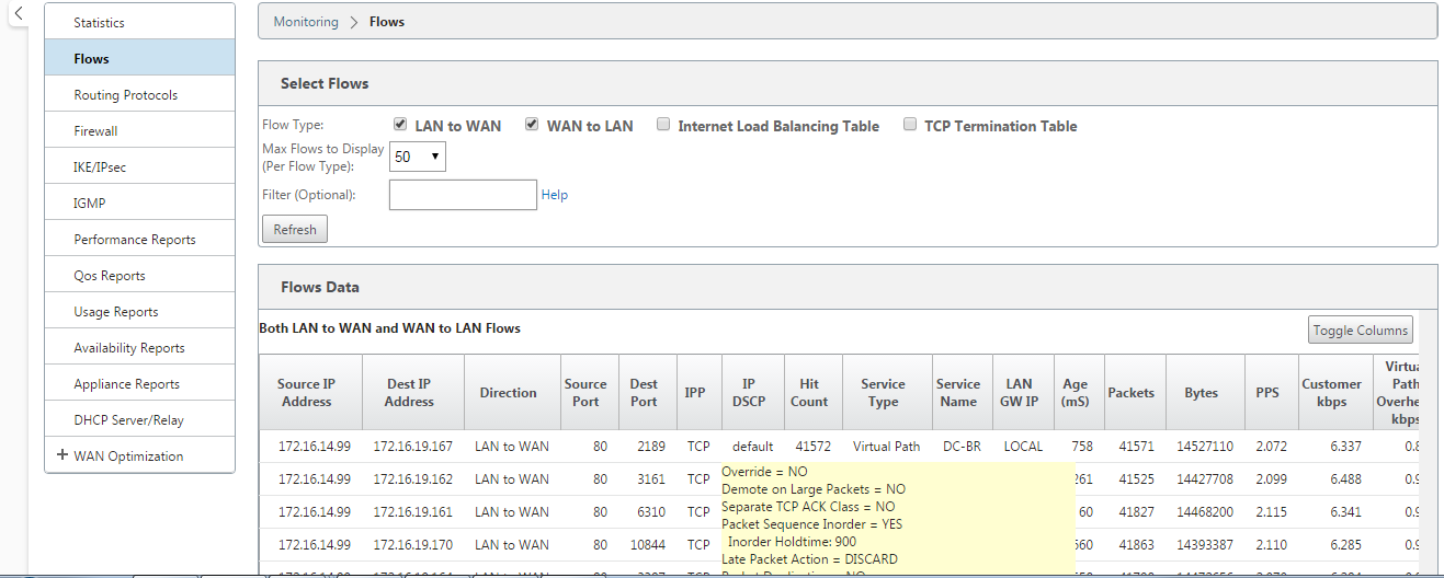
The DPI application object name on the monitoring flow is stored and displayed in the SD-WAN GUI Monitoring -> Flows page. A tooltip is displayed to identify the DPI application.


Monitoring Path information for traffic flow in SD-WAN GUI
It is possible that based on the incoming traffic rate demanding bandwidth, one or more paths are required to process the traffic.
For determining how path mapping is performed, review the following scenarios:
Load Balanced Transmission mode:
The following figure illustrates the scenario when traffic is initiated and all paths are good, one best path is chosen as bandwidth demand is enough to be served by one path. You notice that only one path DC-MCN-Internet -> BR1-VPX-Internet is chosen and the type of transmission type is displayed as Load Balanced.

The following figure illustrates when traffic is flowing, and the WAN attributes of the path are degraded, you notice that a new path is chosen for processing traffic without disruption. In this case, the path mapping feature allows you to indicate that the current best path processing the traffic is DC-MCN-Internet2 -> BR1-VPX-Internet and the last best path that processed the traffic is DC-MCN-Internet -> BR1-VPX-Internet.
The last best path in this example is an indicator of which path served the connection earlier.

The following figure illustrates that when traffic is ongoing and more than one path is chosen for traffic processing due to demand in bandwidth, as shown below, more than one path is chosen when the traffic is being sent. Unlike in the case above, here there may be more than two paths also serving the traffic but in the GUI only the two best paths that is currently serving the traffic is displayed.
Observe DC-MCN-Internet->BR1-VPX-Internet, DC-MCN-Internet2->BR1-VPX-Internet being the two paths shown in the Flows Data table.
Note
As indicated, only max two paths in the flows table are displayed.

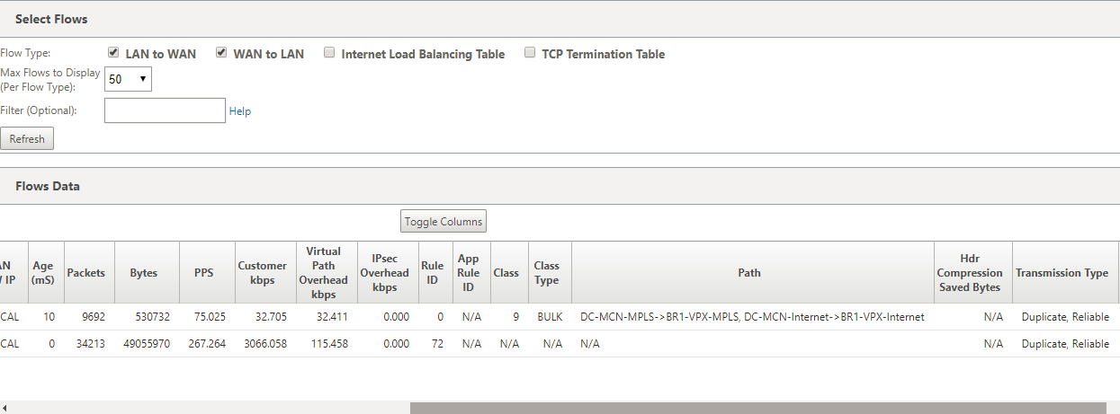
The following figure illustrates that when traffic is still flowing, if the current best path which is DC-MCN-Internet->BR1-VPX-Internet is unavailable/inactive/degraded in WAN attributes, the current best path chosen will appear first in the path section of Flows Data table followed by the last best path which is serving the traffic.
Since the DC-MCN-Internet->BR1-VPX-Internet was not best anymore, a new current best path was chosen by the system as DC-MCN-MPLS->BR1-VPX-MPLS, and the last best path that is actively serving connection along with current best path is DC-MCN-Internet2->BR1-VPX-Internet as both are needed for the current traffic demand of bandwidth.

Duplicate Transmit Mode
General packet duplication mode ensures that two paths are initially taken for processing packets of the same connection to ensure reliable delivery by duplicating packets across two separate paths.
For Path Mapping, you notice that two paths being taken in the path section of the flow table as long as two paths exist to process flows by duplicating.
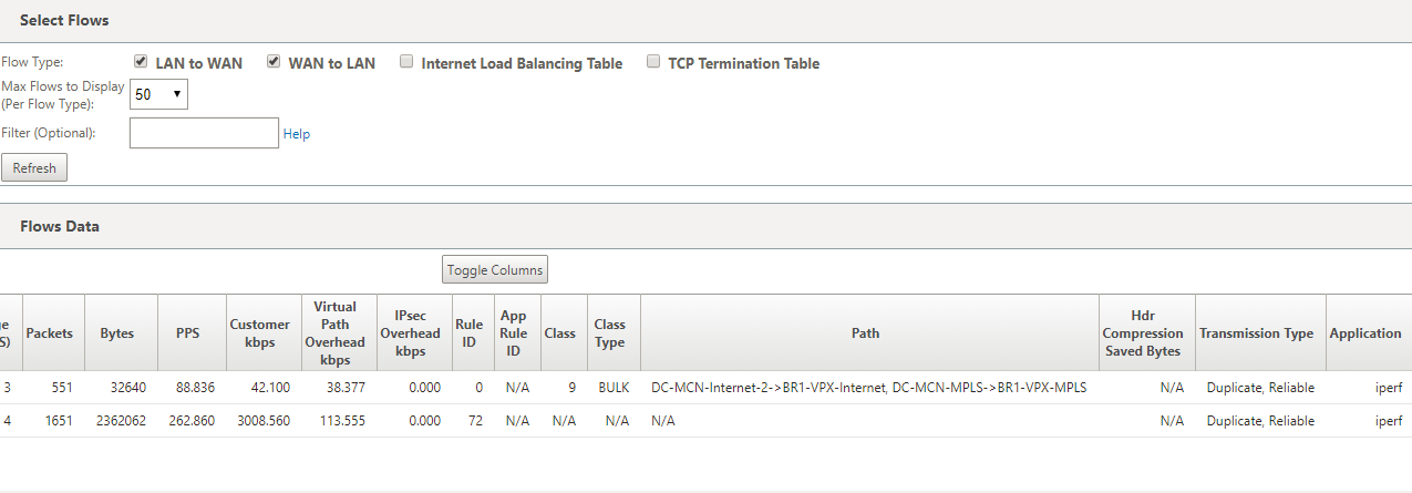
The following figure illustrates that wen traffic is flowing, it can be noticed that two paths are shown to be processing the traffic. Unlike any other mode, even if traffic demands less bandwidth that can be provided by just one path, this mode will always duplicate traffic across two paths for reliable application delivery.
You notice in the figure below, two paths in the path section of the Flows Data table; DC-MCN-Internet2->BR-VPX-Internet, DC-MCN-MPLS->BR1-VPX-MPLS.

The following figure illustrates that when traffic is flowing, if one of the current best paths becomes inactive, another path is chosen and there still be two paths as part of the path section in the Flows Data table.

Persistent Path Transmit Mode
Persistent path transmit mode helps to retain packets of a flow based on path latency impedance.
The following figure illustrates only one path which is the best path currently handling the flows and its packets. There is no demand of bandwidth and one path serves it all. Currently there is only one best path which is DC-MCN-Internet->BR1-VPX-Internet.

The following figure illustrates that if the path DC-MCN-Internet->BR1-VPX-Internet becomes latency prone or is disabled, you notice that new path takes effect and the current path DC-MCN-Internet->BR1-VPX-Internet becomes the last best path.
So the new path section shows DC-MCN-MPLS->BR1-VPX-MPLS, DC-MCN-Internet->BR1-VPX-Internet.

In persistent mode, there can be more than one path chosen to process traffic. In that case, the GUI displays both the paths with best and next best in the path section of the flow table from the beginning of the traffic flow.
The following figure illustrates that the flow initially only needs more than two paths and they stay persistent as long as there is no path latency impedance crossing (50 ms). The two paths taken are shown as; DC-MCN-Internet->BR1-VPX-Internet, DC-MCN-MPLS->BR1-VPX-MPLS.

Assume that one of the best paths DC-MCN-Internet goes into high latency or is disabled. This makes a new path appear and the new path may be the best path or could be the second best path based on the decision of path selection at that instant of time.
