NetScaler SDX 17000
Welcome to the next-generation NetScaler SDX 17000 platform. This section provides comprehensive instructions on how to deploy your appliance efficiently and configure it for optimal performance.
The SDX 17000 2U platform represents the latest advancement in NetScaler technology, featuring enhanced processing power, improved connectivity options, and robust management capabilities.
Key specifications
| Component | Specification |
|---|---|
| Processor | Intel Xeon 5th generation processor, 2x sockets, 24 cores / 48 threads per socket |
| Total Logical CPUs | 96 (2 sockets x 24 cores x 2 threads per core) |
| System Memory | 256 GB DDR5 ECC RDIMM |
| Boot Storage (RAID-1) | 2x 960 GB NVMe SSD (slots 1 and 2) |
| VM Storage (RAID-1) | 4x 800 GB NVMe SSD (slots 3 to 6) |
| Data Connectivity | 2x Quad-port 50G SFP56 NIC (PCIe 4.0 x16) and 2x Dual-port 200G QSFP56 NIC (PCIe 5.0 x16) |
| Management Ports | 2x 1 GbE RJ45 (MGMT 0/1 and 0/2) and 1x dedicated LOM port |
| Power Supplies | 2x CRPS PSUs, redundant N+1, hot-swappable, up to 1600 W each |
| BMC / IPMI | Dedicated BMC for out-of-band management |
| Form Factor | 2U, EIA 310-D 19-inch rack compatible, 88 mm height |
Prepare for installation
Before installing your new appliance, carefully unpack the unit and verify that all the components are present. The only tools required for installing the appliance are a Phillips screwdriver, a flathead screwdriver, and a cage nut insertion tool (if installing into square-hole racks). Your NetScaler 2U package should include the following items:
- 1x NetScaler SDX 17000 appliance
- 1x standard 4-post rail kit (19-inch rack compatible), which includes:
- Left rail (x1)
- Right rail (x1)
- Mounting screw kit (includes M4x4L, M4x6L, M3x6L, M5x20L screws)
- Rackmount ear kit (x1)
The included accessory kit contains essential connectivity hardware, including two power cords to support redundant power supply operation.
Notes:
Rail kit compatibility varies by rack manufacturer and configuration. If the provided rail kit does not fit your specific rack infrastructure, contact your NetScaler sales representative immediately to obtain an appropriate alternative mounting solution.
Before proceeding, examine all components for shipping damage. Report any damaged items to your carrier and NetScaler support before beginning the installation process.
Infrastructure requirements
- Ensure that the 19-inch rack has a minimum of 550 mm depth clearance and 2U available height (88 mm).
- Proper airflow management with front-to-rear cooling path.
- Adequate weight support (system weight: 38 lbs).
Network requirements
- Administrative LAN switch port available for MGMT 0/1 (1 GbE RJ-45).
- Dedicated out-of-band management network or LOM/IPMI access.
- Appropriate network cables (Cat5e or Cat6 for management, fiber, or DAC for data).
- 50 GbE capable switch for SFP56 data ports; 200 GbE capable switch for QSFP56 data ports.
Power requirements
- Dual power sources (recommended for N+1 redundancy).
- Frequency operating range: 47 Hz – 63 Hz.
- Adequate power capacity (full load 100 V: 806 W / 240 V: 765 W).
- PSU input connector: IEC320-C14 (Male).
- Required power cord: IEC320-C13 to NEMA 5-15P (or regional equivalent).
- Rating: Minimum 10 A / 250 V.
Detailed AC input voltage specifications
| Voltage Range | Minimum | Rated Operating Range | Maximum | Brown Out | Brown In |
|---|---|---|---|---|---|
| 115 V Range | 90 Vrms | 100-127 Vrms | 140 Vrms | 75 Vac+/-4 V | 85 Vac+/-4 V |
| 230 V Range | 180 Vrms | 200-240 Vrms | 264 Vrms | N/A | N/A |
Maximum input current requirements
| Input Voltage Range | Maximum Current |
|---|---|
| 100 Vac – 127 Vac | 12 A |
| 200 Vac – 240 Vac | 10 A |
Management station requirements
-
Workstation or laptop (Windows or macOS) with network connectivity.
-
Web browser with JavaScript and HTML5 support (Chrome, Firefox, Safari, or Edge).
-
Terminal emulator software for CLI access.
-
Administrative privileges for network configuration.
Hardware platform
Front panel components
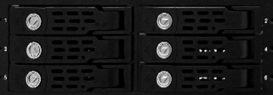
The SDX 17000 front panel provides management interfaces, NVMe drive bays, data ports, and power controls. Six hot-swappable NVMe bays are located at the front left of the panel.
NVMe drive bay assignments:
-
Slots 1–2: Two 960 GB NVMe SSDs configured as RAID-1 for the SDX OS/system volume.
-
Slots 3–6: Four 800 GB NVMe SSDs allocated as two independent RAID-1 pairs for the VM datastore.
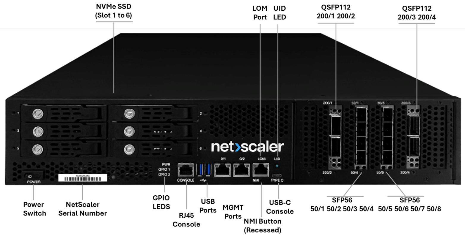
Front panel component description
| Label | Component Type | Technical Specification | Primary Function |
|---|---|---|---|
| CONSOLE | RJ-45 Console Port | RS-232 compatible, 9600-8N1 | Primary serial console for direct system access |
| MGMT 0/1 & 0/2 | Dual Ethernet Ports (1000Base-T) | 1000Base-T, autonegotiate | Primary/secondary in-band management |
| LOM | Dedicated IPMI Port | Intelligent Platform Management Interface, IPMI 2.0, Redfish 1.15.1 | Out-of-band hardware monitoring and control |
| NMI | Pinhole Button | Non-maskable interrupt | Force kernel core dump for crash analysis |
| PWR | Soft-push Button (4 sec on/off) | Power management | Power on / graceful shutdown control |
| TYPE-C | USB Type-C console port (optional) | Alternate console (not used in standard deployment) | Secondary console and debug interface |
| UID | Locator LED | Blue LED indicator | Visual system identification in rack |
| GPIO1/GPIO2 | User-defined GPIOs | General-purpose I/O | Not utilized; disabled by default on 2U platform |
| NVMe Slots 1-2 | U.2/U.3 NVMe SSDs | 960 GB per drive (2x), RAID-1 | SDX OS boot volume |
| NVMe Slots 3-6 | U.2/U.3 NVMe SSDs | 800 GB per drive (4x), RAID-1 | VM datastore (two pairs) |
| 50/1-50/8 | SFP56 Data Ports | 50 GbE network interface card (NIC) | Two 4-port SFP56 with PCIe 4.0 x16 |
| 200/1-200/4 | QSFP56 Data Ports | 200 GbE network interface card (NIC) | Two 2-port QSFP56 with PCIe 5.0 x16 |
Rear panel components
The rear panel houses the dual Common Redundant Power Supply (CRPS), cooling fans, a secondary Unit Identification (UID) LED, a PSU alarm mute button, a VGA output port, and a rear power button.
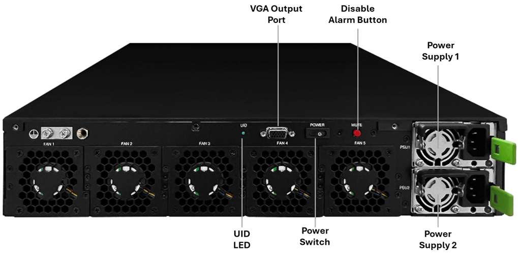
Panel component description
| Component | Technical Details | Operational Characteristics | Service Information |
|---|---|---|---|
| PSU1/PSU2 | CRPS PSU, up to 1600 W each | Redundant N+1 configuration | Hot-swappable during operation |
| Rear UID LED | Blue LED locator | Blue LED indicator | Remote chassis identification |
| PSU Alarm Mute | Red push-button | Silences audible alarm on PSU fault or loss of AC input | Press once to acknowledge PSU alarm |
| VGA Output | DB-15 (female D-sub) | System video output | Local KVM connection; also accessible via LOM |
| Rear Power Button | Soft-push, optional | Mirrors front panel power button function | Dual power control access |
| Fan Modules | 5 system fans | Smart fan intelligent control by BMC | Note: No field-replaceable Fan FRU |
Install the hardware
Rack-mount the appliance
Perform the following procedure to ensure proper appliance mounting and system performance.
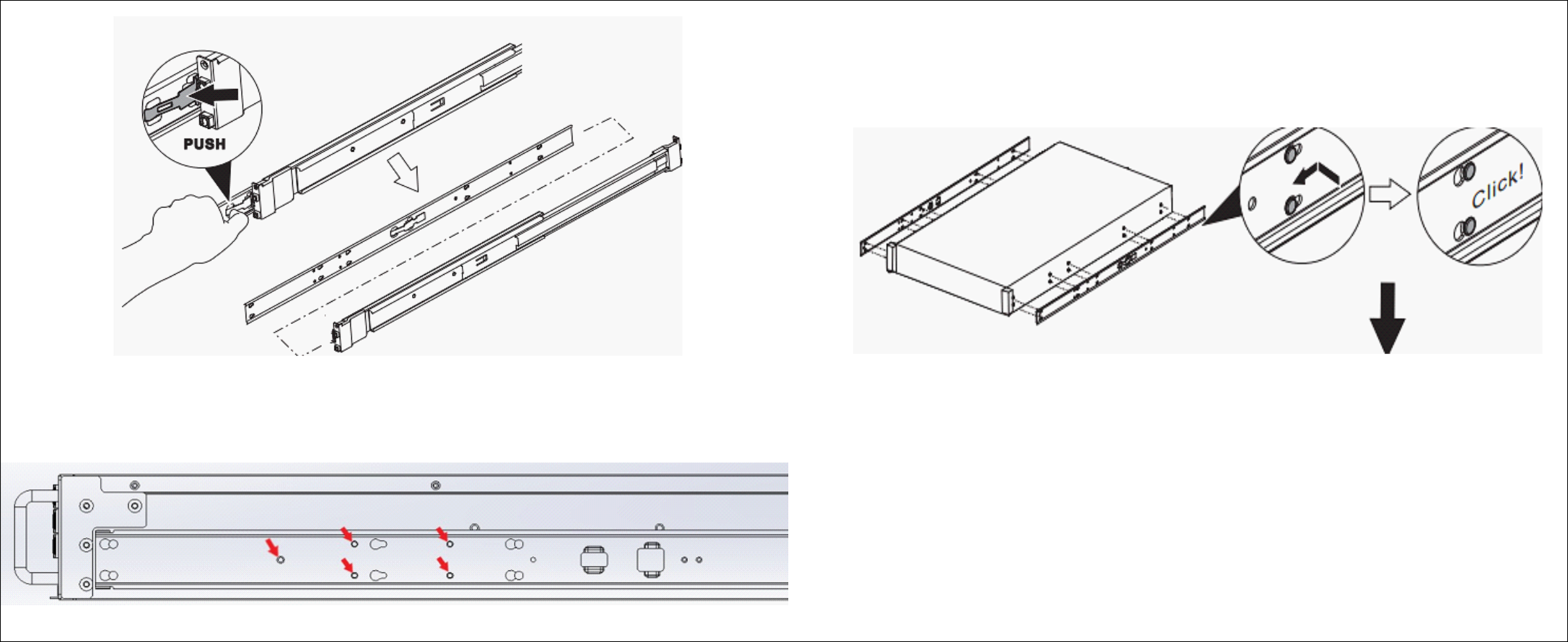
Remove the inner rails from the rail assembly
-
Pull the white disconnect tab to release and detach the inner rail member from each slide rail.
-
With the stamped text facing outward, align the inner rail with the chassis mount points, using the black reference markers on both sides of the chassis.
-
Slide the rail toward the rear until it clicks firmly into the locked position.
-
Fasten each inner rail using the provided M4x4L screws. Use five screws per side for a total of ten.
-
Repeat this process for both the left and right sides of the chassis.
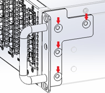
Chassis mounting ear installation
-
Attach rack mount ears to both the left and right sides of the chassis front.
-
Align the ears with the designated screw holes on the chassis.
-
Secure each ear with M4x6L screws using four screws per side.
-
Verify that the ears are flush and do not obstruct front panel access.
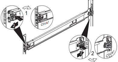
Outer slide rail assembly installation
-
Align the mounting brackets with the rack post holes at the selected 2 U-height.
-
Insert the rail mounting mechanism into the rack posts until it engages.
-
Listen for an audible “click” to confirm that the rail is properly seated and locked.
-
Ensure both the front and rear mounting points are securely attached to the posts.
-
Verify that the rails are level and parallel using the numbered rack post markings.
-
Repeat this process for both the left and right outer rail assemblies.
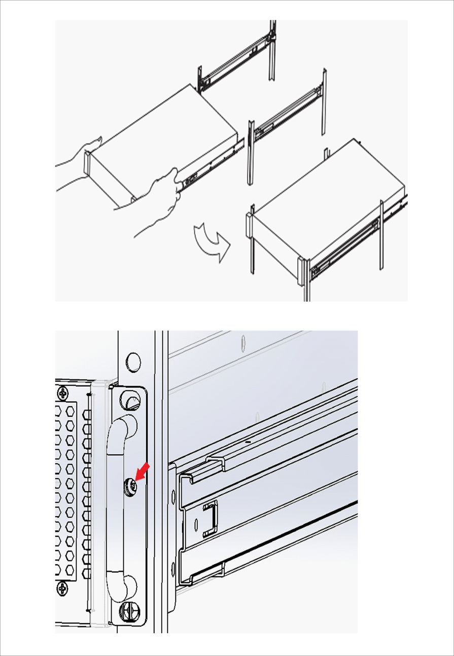
Mount the chassis into the rack
-
Carefully align the chassis-mounted inner rails with the rack-mounted outer rails.
-
Smoothly slide the system into the rack until the locking mechanism engages.
- If necessary, apply light, even pressure to ensure the unit locks securely into place.
- Secure each front ear to the rack post using one M5x20 screw per side.
Safety requirements
For safety and equipment durability, ensure that the following requirements are met:
-
Maintain a minimum of 2 inches of clearance at the front and rear of the chassis to ensure proper ventilation.
-
Verify the rack’s weight capacity before installation and ensure that the rack is stable and properly secured to the floor.
-
Use proper lifting techniques. The system weight is approximately 38 lbs.
-
Strictly follow electrical safety procedures when connecting the appliance to a power source.
Airflow management
The 2U platform is designed for front-to-rear airflow. Unobstructed passage is required for optimal cooling performance. Restricted airflow results in thermal overheating and the automatic activation of system protection mechanisms (throttling or shutdown).
Network and power connections
Connection sequence
Perform the following producure to ensure proper system initialization and to prevent configuration conflicts.
-
Management network connectivity
-
Connect the 0/1 MGMT port to your administrative LAN by using a Cat5e/Cat6 Ethernet cable.
-
Ensure that the network switch port is configured to support auto-negotiation.
-
Verify network connectivity and ensure that the correct VLAN configuration is applied, if applicable.
-
Document the assigned IP address and network parameters for future reference.
-
-
Out-of-Band (OOB) management setup
- Connect the Lights-Out Management (LOM) port to a dedicated out-of-band (OOB) management network.
- Use separate network infrastructure from production traffic.
- Leave the LOM port in dedicated mode operation (factory default).
-
Data port configuration
- Install appropriate SFP56 transceivers (50 GbE ports: 50/1-50/8) or QSFP56 transceivers (200 GbE ports: 200/1-200/4).
- Match the transceiver type to switch port capabilities. Use Citrix-qualified transceiver MPNs for guaranteed interoperability.
- Connect fiber or DAC cables to data ports as required.
- Verify that the cable specifications match the port capabilities (50 GbE and 200 GbE).
-
Power system connection
-
Plug the first power cord into the PSU1 input receptacle.
-
Plug the second power cord into the PSU2 input receptacle.
- Connect the unit to independent power feeds where possible to ensure N+1 redundancy.
- Ensure that the power source meets requirements (100–240 VAC, 50–60 Hz).
-
-
System startup
- Press the front panel power button to initiate the boot sequence.
- Observe the front panel LEDs; the power LED should illuminate solid green.
- Verify both PSU LEDs are solid green within ten seconds of power-on.
- Allow the full boot cycle to complete (approximately 4–5 minutes) before accessing the system.
Power supply status indicators
The CRPS power supplies provide comprehensive status monitoring through integrated LED indicators located on each unit’s faceplate.
PSU LED indicator status:
| LED Indicator | PSU State | System Impact | Action Required |
|---|---|---|---|
| Solid GREEN | AC present, all DC rails active under load | Normal operation | None - normal |
| 1 Hz Blink GREEN | AC present, 12Vsb active including 5Vsb for BMC power, main rails idle | Redundant standby (N+1) | None - normal |
| Solid AMBER | AC input lost or disconnected | Lost redundancy (if N+1) or system down | Check AC power connection |
| 1 Hz Blink AMBER | OCP/OVP/OTP warning threshold reached | Degraded PSU operation/Potential shutdown | Verify PSU cooling and airflow |
| Solid AMBER | Critical Fault (OCP/OVP/OTP tripped) | PSU shutdown for protection | Replace the PSU immediately |
System access and configuration
SVM GUI access method
The web-based Service VM (SVM) management interface provides a centralized graphical user interface (GUI) for platform configuration and monitoring. Through the SVM GUI, administrators can manage key system functions and access platform resources associated with the SVM and the XenServer Dom0 hypervisor.
Platform-specific access information
- Management through virtualized service interfaces
- Management Service VM: 192.168.100.1 with 255.255.0.0 (/16) subnet mask
- XenServer hypervisor (DOM0): 192.168.100.2 with 255.255.0.0 (/16) subnet mask
- NSIP pool range: 192.168.100.10 to 192.168.100.100 for NetScaler instances
Perform the following steps to initialize the appliance
- Network preparation
- Connect your management workstation to the MGMT 0/1 port or a port on the same management VLAN.
- Set a static IP address on the workstation in the 192.168.100.X/16 range (for example, 192.168.100.50).
- Verify the network path by performing a ping test to the default SVM IP address: 192.168.100.1.
- Ensure that any local firewalls allow HTTPS (port 443) traffic to the appliance.
- Browser initialization
- Open a Web browser (Chrome, Firefox, Safari, or Edge).
- Enter the URL
https://192.168.100.1(Management Service VM).Note:
Accept a security certificate warnings (self-signed certificate) to proceed to the login page.
- Initial authentication
- Username:
nsroot. - Password: Enter the system serial number exactly as it appears on the physical chassis label (case-sensitive).
-
Click Login or press Enter.
On successful authentication, the system redirects you to the Initial Configuration Wizard.
- Username:
-
Setup wizard configuration
The Setup Wizard guides you through the following essential parameters:
-
Management service IP address (NSIP): Assign a static IP address for ongoing SVM access.
-
XenServer IP address: Assign the DOM0 management address.
-
Subnet mask and default gateway: Configure these for your network segment.
-
DNS server: Enter the primary DNS IP address.
-
Hostname: Assign a unique, descriptive hostname to identify the appliance on the network.
-
Administrative password: Change the default password to a strong, secure administrative password.
-
Common default IP address configuration
| Interface or Service | Default User Login Credentials | Default IP Address | Subnet Mask or Gateway | Description |
|---|---|---|---|---|
| Management Service (SVM) (0/1) | nsroot / product SN | 192.168.100.1 | 255.255.0.0/16 | Management Service is the management interface of NetScaler SDX for provisioning and monitoring VPX instances |
| XenServer (DOM0) | root / product SN | 192.168.100.2 | 255.255.0.0 /16 GW: 192.168.0.1 | DOM0 is the hypervisor control domain (based on Linux) that interfaces with system hardware. Note: The product serial number as the default password for DOM0 is only valid after Management Service initialization. |
| XenServer (Management Service virtual port 0/2) | nsroot / product SN | 169.254.0.10 | 255.255.0.0 /16 | Management Service internal default IP address for 2U platform. Used for internal DOM0 and Management Service communication |
| LOM or IPMI Port | nsroot / product SN | 192.168.1.3 | 255.255.255.0/24 | Out-of-band management IPMI, Redfish, remote iKVM, power control |
Console connection setup by using the CLI
-
Physical connection
-
Connect an RJ-45 serial cable to the console port on the front panel.
-
Connect the other end of the cable to your workstation’s serial port or to a USB-to-serial adapter.
Ensure that the cable is seated firmly at both ends to prevent data corruption or character “scrambling” during the session.
-
-
Terminal emulator configuration
Open your terminal emulation software (such as PuTTY, Tera Term, or SecureCRT) and configure the following settings:
Setting Value Baud Rate 9600 bps Data Bits 8 Parity None Stop Bits 1 Flow Control None (Disabled) Terminal Type ANSI Putty Keypad Mode VT 100 -
Session establishment
-
Open the terminal emulator application.
-
Establish a connection by using the configured settings.
-
Press Enter to trigger the login prompt if it does not appear automatically.
Wait for the login prompt to display.
-
-
Authentication process
-
At the login prompt, type
nsroot. -
At the password prompt, type the system serial number (found on the chassis label).
-
On successful authentication, the system displays the NetScaler command prompt.
-
Note:
All login credentials are case-sensitive.
NetScaler SDX Management Service sample configuration
-
Management Service shell access
- SDX Management Service initial network configuration

- SSH connection
- From your management laptop, initiate an SSH session to the Management Service IP address :
ssh nsroot@192.168.100.1 - Authenticate using the username as nsroot and the password as the product serial number.
- Log in to the NetScaler CLI prompt, run the
shellcommand.
You can verify that you have successfully gained access when the prompt changes to bash-3.2#.
- From your management laptop, initiate an SSH session to the Management Service IP address :
- SDX Management Service initial network configuration
-
Configuration file verification
-
Access the configuration file: From the bash-3.2# prompt, run the
cat /flash/mpsconfig/svm.confcommand to display the contents of the Management Service configuration file. -
Review default contents: Ensure the output matches the standard default settings, which include the following parameters:
Default svm.conf output:
- ifconfig 0/2 down
- ifconfig 0/2 delete
- arp -d -a
- route flush
- ifconfig 0/1 192.168.100.1 netmask 255.255.0.0
- ifconfig 0/2 169.254.0.10 netmask 255.255.0.0
- /mps/changenameserver.sh 127.0.0.2
-
Verify XenServer Connectivity: Confirm the XenServer IP address is listed at the end of the file as:
#XenServer: 192.168.100.2.Note:
The SDX 17000 uses virtual port 0/3 for the SVM internal IP address (169.254.0.10). The port number differs from the SDX 1U platform, which uses port 0/2. Ensure that the svm.conf file reflects port 0/3 for the 2U platform.
-
-
Network configuration modification
-
Launch the configuration utility: From the bash shell environment, initiate the interactive network setup tool by running the command:
/mps/networkconfig. -
Interactive configuration menu: After launching the utility, the following menu appears:
----------------------------------------------------------------------------

NetScaler SDX initial network configuration
This menu allows you to set and modify the ini0al IPv4 network addresses.
The current value is displayed in brackets ([]).
Selecting the listed number allows the address to be changed.
----------------------------------------------------------------------------
1.  Management Service Host Name [ns]

2.  Management Service IPv4 address [192.168.100.1]

3.  XenServer IPv4 address [192.168.100.2]

4.  Netmask [255.255.0.0]

5.  Gateway IPv4 address []

6.  DNS IPv4 Address [127.0.0.2]

7.  Cancel and quit

8.  Save and quit
<!--NeedCopy-->
Note:
The current values are shown in square brackets. Press the corresponding number (1–6) to modify each parameter.
- Navigate the interactive menu: Use the menu options (1–6) to modify the following parameters as required for your network environment.
- Save changes: Once all parameters are updated, select option 8 (Save and quit) to commit your changes.
Note:
The Service VM automatically applies the new network configuration during the next startup process.
-
-
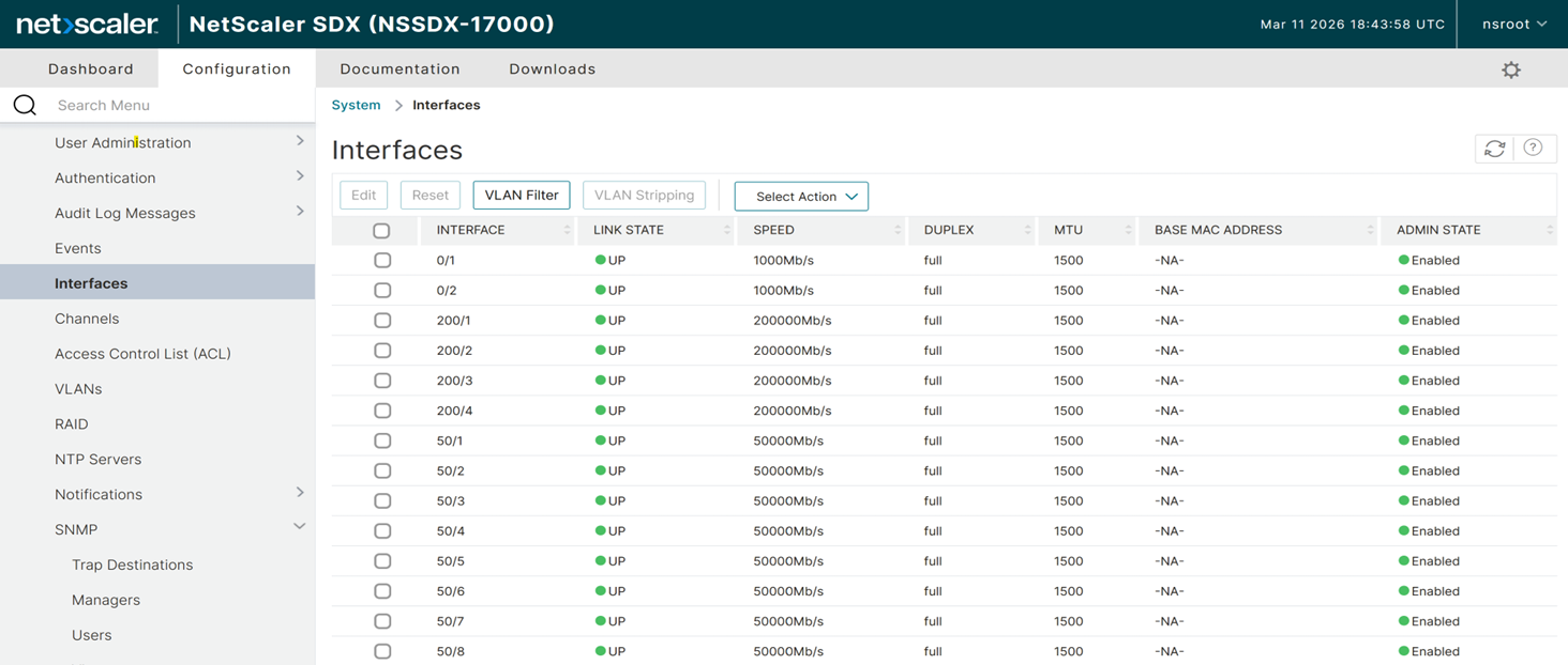
Management Service GUI access verification
- Test connectivity: Open a web browser and enter the new Management Service IP address in the address bar.
-
Login: Authenticate using the username
nsrootand the product serial number as the password.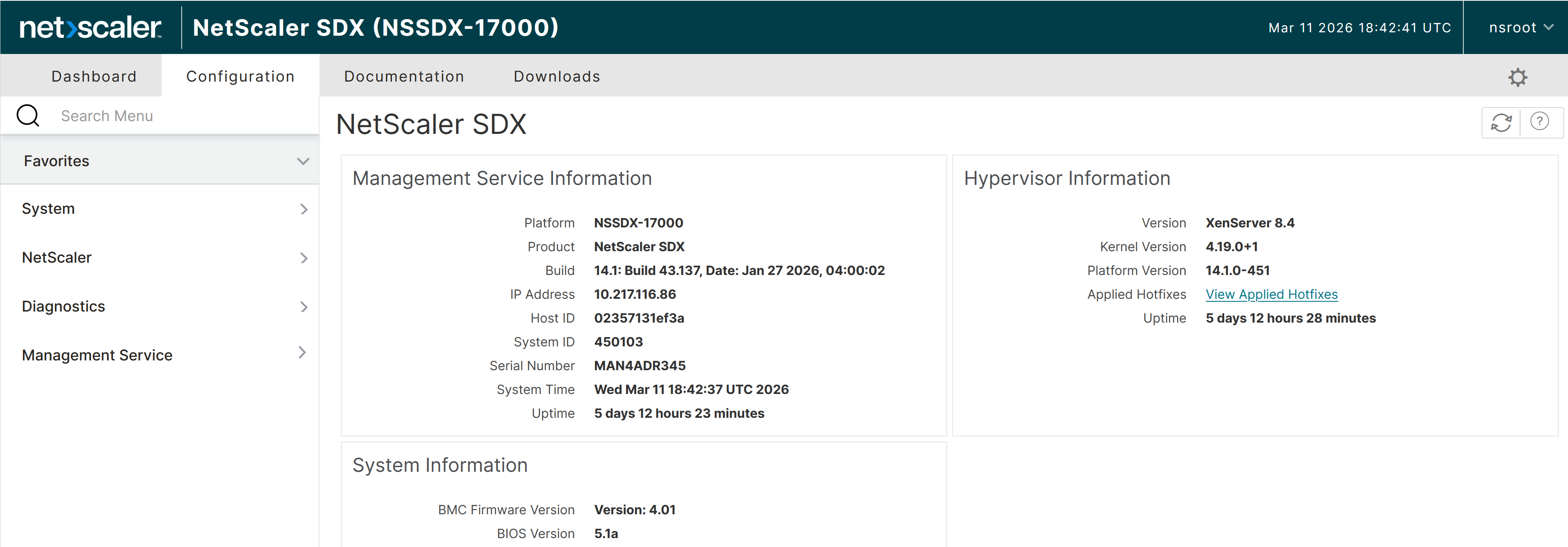
- Navigate to Configuration > Interfaces to view all the management and data interfaces on SDX 17000 from the SVM GUI.
-
DOM0 console access
- Power on the NetScaler SDX appliance and connect your management laptop to the RJ45 console port.
- Set your terminal emulator (PuTTY) to 9600 baud, 8 data bits, None for parity, 1 stop bit, and None for flow control.
- Log in to DOM0 using the username root and the product serial number as the password.
- Confirm that you have reached the DOM0 command line when the prompt displays as
[root@netscaler-sdx ~]#.
System specifications
Hardware configurations
The SDX 17000 platform integrates enterprise-grade hardware built to deliver high-performance applications with consistent reliability.
Core system architecture
| Component Category | Specification Details | Performance Characteristics |
|---|---|---|
| Regulatory Model | 2U3P3A | FCC and international compliance designation |
| Processor Architecture | Intel Xeon 5th generation processor | 2 sockets, 24 physical cores / 48 threads per socket; 96 logical CPUs total at 2.2 GHz |
| Platform Chipset | Intel C741 PCH | Advanced platform controller hub |
| BMC Controller | Baseboard Management Controller with IPMI 2.0 | Remote KVM, hardware monitoring, power control |
| System Memory | 256 GB DDR5 5600 ECC RDIMM | 8x 32 GB modules, error correction enabled |
| Primary Storage | 2x 960 GB NVMe U.2/U.3 (slot 1 and 2) | Configured as RAID-1 for SDX OS and system volume |
| VM Storage | 4x 800 GB NVMe U.2/U.3 (slot 3 to 6) | Two independent RAID-1 pairs for VM datastore |
| Management Connectivity | Two 1 GbE RJ45 (1000Base-T) | MGMT 0/1 (primary), MGMT 0/2 (secondary) |
| 50G Data Connectivity | Two 4-port SFP56 NICs | PCIe 4.0 x16 - ports 50/1-50/8, 8 total 50G ports |
| 200G Data Connectivity | Two 2-port QSFP56 NICs | PCIe 5.0 x16 - ports 200/1-200/4, 4 total 200G ports |
| NUMA Topology | 2 NUMA nodes | Each NUMA node corresponding to one CPU socket |
Power and environmental specifications
Power system specifications
| Parameter | Specification | Operating Range | Notes |
|---|---|---|---|
| Power Supply Configuration | 2x CRPS PSUs | Redundant N+1 operation | Hot-swappable, up to 1600 W each |
| Input Voltage Range | 100-240VAC | Universal input compatibility | Auto-sensing |
| Input Frequency | 50-60 Hz | Standard utility frequency | +/-3Hz tolerance |
| Input Current | 100-127Vac: 12A max 200-240Vac: 10A max | Variable by input voltage | Maximum ratings |
| Typical System Power Consumption | 465 W | Normal operational load | Steady-state operation |
| Maximum System Power Consumption | 806 W at 100 V / 765 W at 240 V | Peak system utilization | Full load with both PSUs active |
Environmental specifications
| Environment Factor | Operating Range | Storage Range | Critical Limits |
|---|---|---|---|
| Ambient Temperature | 0-45 deg C (32-113 deg F) | -40 to 70 deg C | 50 deg C absolute maximum |
| Relative Humidity | 10-90% RH | 10-95% RH | Non-condensing |
| Operating Altitude | 0-5,000 m | 0-15,200 m | Derated above 8,000 m |
| Typical System Airflow (front-to-back) | ~126.54 CFM | N/A | Full load at nominal 25 deg C ambient |
| Maximum System Airflow (front-to-back) | ~214.83 CFM | N/A | Full load at elevated temperature |
Physical specifications
| Dimension | Measurement | Standard Compliance |
|---|---|---|
| Width | 443 mm (17.4 in) | EIA 310-D 19-inch rack |
| Depth | 550 mm (21.7 in) | Standard server depth |
| Height | 88 mm (3.5 in) | 2U rack unit |
| System Weight | 38 lbs | Approximate operational weight |
| Package Weight | 52 lbs | Shipping configuration |
System LED status
The system provides real-time status monitoring by using the LED indicators located on the front and rear panels.
Front panel LED status
| LED Indicator | Normal Operation | Fault Condition | Description |
|---|---|---|---|
| PWR (Power) | Solid Green | Off | System power and initialization status |
| GPIO1 | Off (default) | N/A | User-defined function (disabled) |
| GPIO2 | Off (default) | N/A | User-defined function (disabled) |
Power supply LED status
| LED Indicator | PSU State | System Impact | Action Required |
|---|---|---|---|
| Solid GREEN | AC present, all DC rails active under load | Normal operation | None - normal |
| 1 Hz Blink GREEN | AC present, 12Vsb active including 5Vsb for BMC power, main rails idle | Redundant standby (N+1) | None - normal |
| Solid AMBER | AC input lost or disconnected | Lost redundancy (if N+1) or system down | Check AC power connection |
| 1 Hz Blink AMBER | OCP/OVP/OTP warning threshold reached | Degraded PSU operation/Potential shutdown | Verify PSU cooling and airflow |
| Solid AMBER | Critical Fault (OCP/OVP/OTP tripped) | PSU shutdown for protection | Replace the PSU immediately |
NVMe SSD tray LED status
Each NVMe tray includes two LEDs. The right LED indicates drive presence and activity. The left LED indicates drive status and is controlled by the NVMe backplane controller through the BMC.
Left LED status indicators:
| Left LED (Location / Status) | LED State |
|---|---|
| Locate/Identify Drive | Yellow Blink at 4 Hz |
Use the LOM web UI (Storage section) to toggle the location LED for a specific NVMe slot (0-5) to identify a drive in a populated rack. Select the target drive and toggle it from OFF (default) to ON (locate active).
Right LED status indicators:
| Right LED (Active / Present) | LED State |
|---|---|
| SSD present and idle | Solid Green |
| Storage data transfer/active | Green, Blinking at 4 Hz |
| No SSD Present or Removed | LED Off |
Additional information resources
- For information about detailed specifications, configuration guides, and troubleshooting procedures, see the NetScaler Hardware Platforms Documentation.
- For information about step-by-step procedures for performing system upgrades and downgrades, see Upgrade and downgrade a NetScaler appliance.
- For information about deploying redundant NetScaler configurations, see Configuring high availability.
Technical support access
- Primary support portal: Customer portal at https://www.netscaler.com/
- Online documentation: Complete technical library at www.docs.netscaler.com
Information required for technical support
Before contacting NetScaler Support, gather the following information to ensure an efficient resolution process:
-
Hardware serial number: Locate this on the physical chassis label.
-
Software version: Provide the current release version and specific build number (Example: Release 14.1 Build 12.35).
-
Problem description: Document the specific issue, including exact error codes, timestamps of the occurrence, and any recent changes to the environment.
-
System configuration: Provide the network environment and relevant configuration files (Example: ns.conf).
-
Log files: Collect the system logs and diagnostic information.