-
-
-
-
Importing and synchronizing StyleBooks from GitHub repository
-
Simplified migration of Citrix ADC application configuration using StyleBooks
-
-
Use ADM log messages for managing and monitoring your infrastructure
-
-
Citrix ADC automation using Citrix ADM in Cisco ACI hybrid mode
-
Citrix ADC device package in Cisco ACI's cloud orchestrator mode
-
This content has been machine translated dynamically.
Dieser Inhalt ist eine maschinelle Übersetzung, die dynamisch erstellt wurde. (Haftungsausschluss)
Cet article a été traduit automatiquement de manière dynamique. (Clause de non responsabilité)
Este artículo lo ha traducido una máquina de forma dinámica. (Aviso legal)
此内容已经过机器动态翻译。 放弃
このコンテンツは動的に機械翻訳されています。免責事項
이 콘텐츠는 동적으로 기계 번역되었습니다. 책임 부인
Este texto foi traduzido automaticamente. (Aviso legal)
Questo contenuto è stato tradotto dinamicamente con traduzione automatica.(Esclusione di responsabilità))
This article has been machine translated.
Dieser Artikel wurde maschinell übersetzt. (Haftungsausschluss)
Ce article a été traduit automatiquement. (Clause de non responsabilité)
Este artículo ha sido traducido automáticamente. (Aviso legal)
この記事は機械翻訳されています.免責事項
이 기사는 기계 번역되었습니다.책임 부인
Este artigo foi traduzido automaticamente.(Aviso legal)
这篇文章已经过机器翻译.放弃
Questo articolo è stato tradotto automaticamente.(Esclusione di responsabilità))
Translation failed!
Create and deploy a service graph
You have to use Cisco APIC service graph templates in APIC to create and deploy the Citrix ADCs. Make sure that you use the ADC function profile while creating and deploying a service graph.
After the graph is configured in the APIC, the APIC automates the device configuration on the basis of the function definitions, device connectivity to the fabric, and the entities configured as part of the graph deployment. The APIC also automates the network configuration, such as VLAN allocation and its binding, as part of the service graph creation, and the configuration is removed once you delete the graph from the APIC.
A service graph is represented as two or more tiers of an application, with the appropriate service function inserted between them. A service graph is inserted between the source and destination EPGs by a contract.
To create a service graph by using the APIC GUI:
-
On the menu bar, go to Tenants > All Tenants.
-
In the Work pane, double-click the tenant’s name.
-
In the Navigation pane, select tenant_name > L4-L7 Services > L4-L7 Service Graph Templates.
-
In the Work pane, select Actions > Create a L4-L7 Service Graph Template.
-
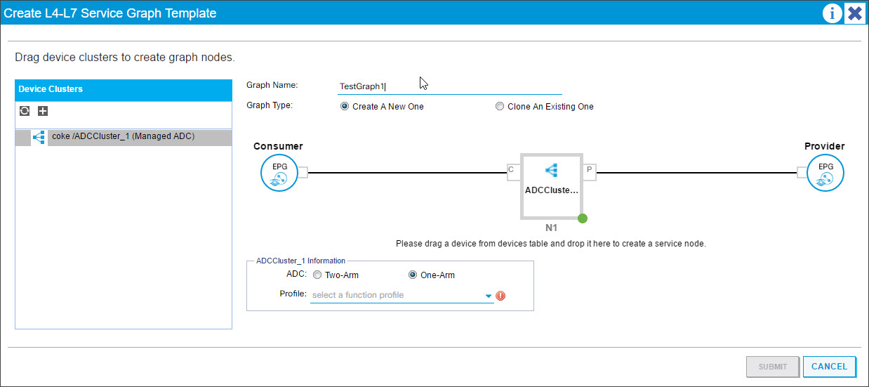
In the Create a L4-L7 Service Graph Template dialog box, in the Device Clusters section, select a device cluster and do the following:
-
In the Graph Name field, enter the name of the service graph template.
-
In the Graph Type field, select Create A New One.
-
From the Device Cluster section, drag the device and drop it between the consumer end-point group and provider end-point group to create a service node.
-
In the <L4-L7device_name information> section, do the following:
-
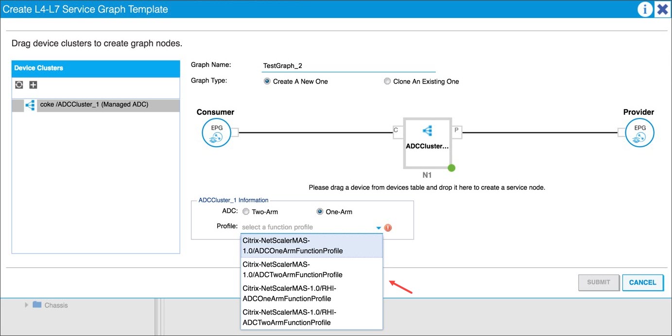
In the ADC field, select One-Arm or Two-Arm, depending on how the Citrix ADC is deployed in the fabric.
-
In the Profile drop-down list, select the function profile provided in the device package.
-
Click SUBMIT.
-
-
-
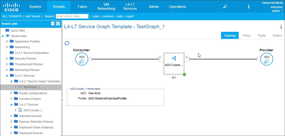
In the Navigation pane, click the service graph template. The screen presents a graphic topology of the service graph template.
Note
The Cisco APIC supports the notion of connectors, and these connectors are visible in the ADCCluster node. The connectors define the network traffic direction and the device script that dynamically binds the allocated VLAN to a virtual IP (VIP) or subnet IP (SNIP) address, depending on whether the connection is external or internal. VLANs are also bound to specific interfaces used for inbound and outbound traffic.
Applying the Service Graph Template to Endpoint Groups
After you have created the service graph template, you need to apply the created service graph template by using the APIC GUI.
To apply the service graph template:
-
On the menu bar, go to Tenants > All Tenants.
-
In the Work pane, double click the tenant’s name.
-
In the Navigation pane, choose tenant_name > L4-L7 Services > L4-L7 Service Graph Templates.
-
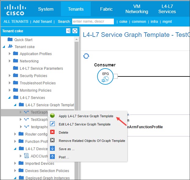
Right-click on the template_name and click Apply L4-L7 Service Graph Template.
-
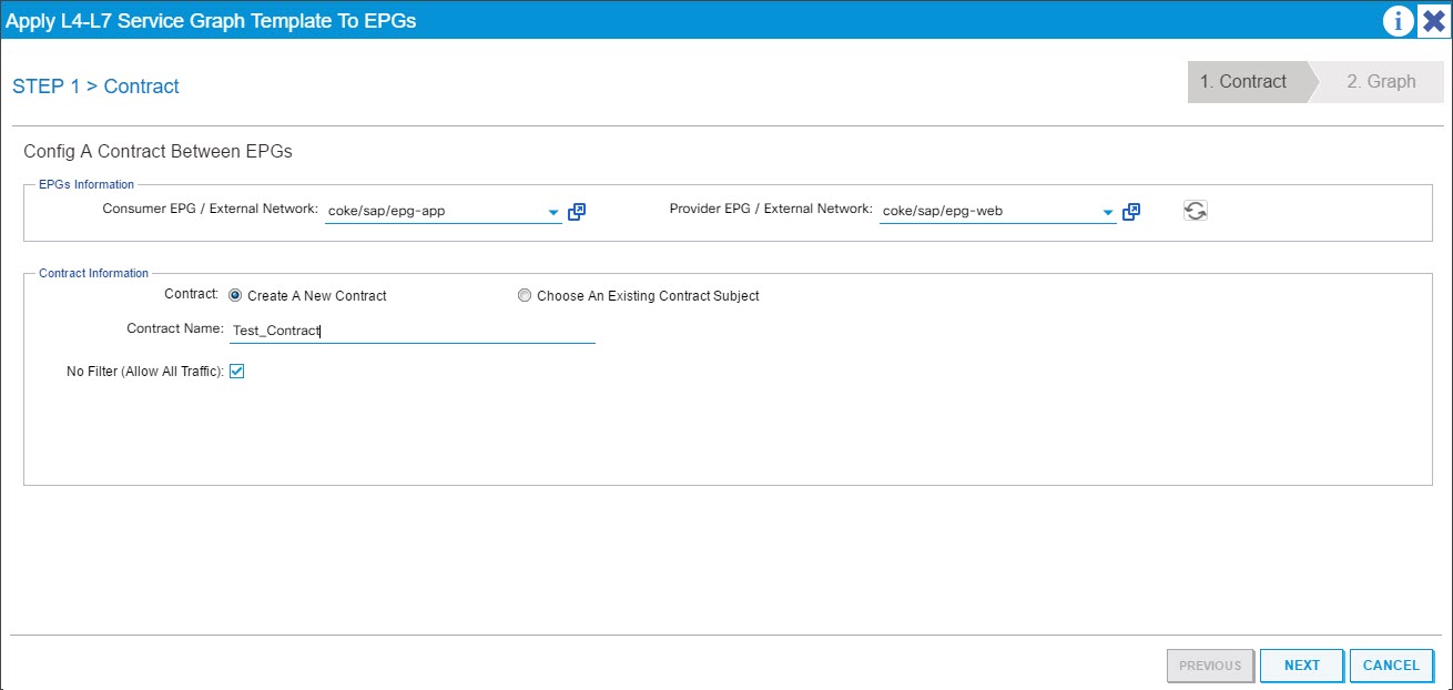
In the Apply L4-L7 Service Graph Template To EPGs dialog box, in the EPG Information section, complete the following fields:
-
In the Consumer EPG/External Network drop-down list, select the consumer endpoint group.
-
In the Provider EPG/External Network drop-down list, select the provided endpoint group.
-
In the Contract Information section, complete the appropriate fields. The contract information is specific to the Cisco APIC and is configured as part of the security policies associated with the EPGs.
-
Click Next.
-
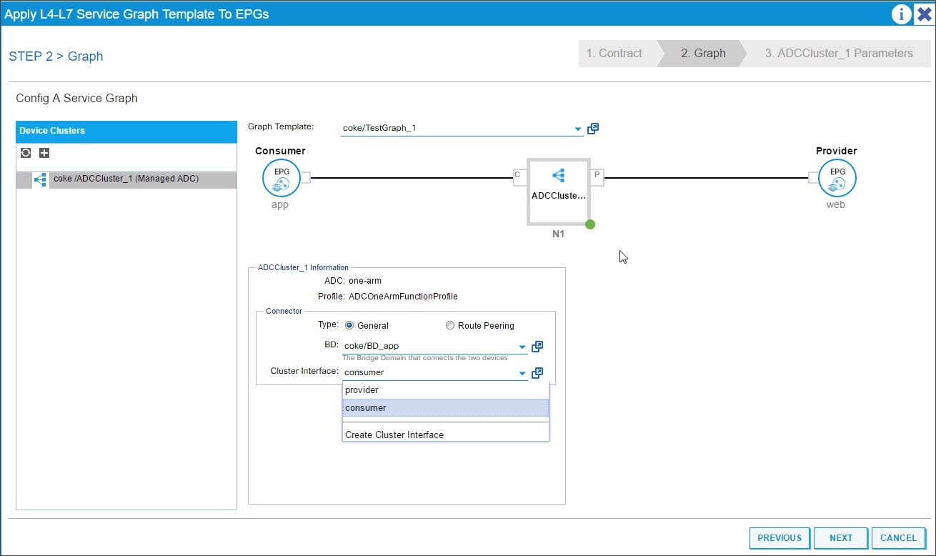
In the Graph Template drop-down list, select the service graph template that you created.
-
In the Connector section, do the following:
-
In the Type field, select General.
-
In the BD drop-down list, select the bridge domain. Connector details are part of the bridge domain that is part of the Cisco APIC infrastructure model.
-
In the Cluster Interface drop-down list, select the appropriate cluster interface for the selected bridge domain.
The Cisco APIC uses the selected bridge domains for data path traffic between the Citrix ADC device and the fabric as required by the selected service graph template.
-
Click Next.
On the Parameters screen, on the Required Parameters tab, enter the L2-L3 specific details, such as the IP address that is mandated by the profile. The other key parameter is the StyleBook name. It can be the built-in StyleBook APIC-HTTP-LB provided in Citrix Application Delivery Management (ADM), or you can provide the name of the SytleBook that you created in Creating a StyleBook for the Application Using Citrix ADM
Note
The StyleBook name links the Service Graph details with the L4-L7 configuration created with Citrix ADM for a given application.
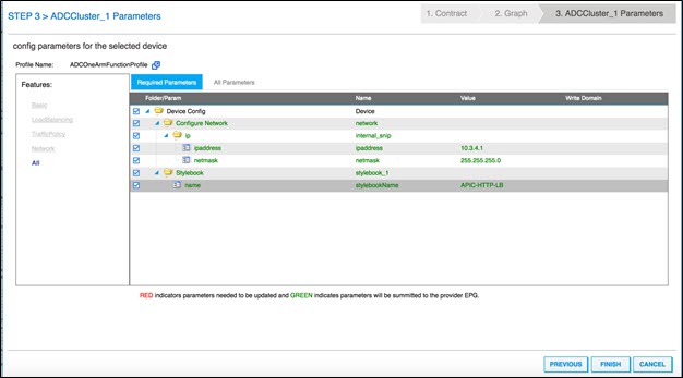
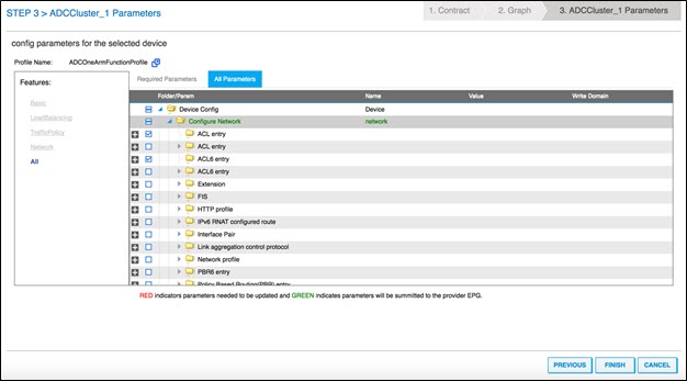
The Cisco APIC GUI allows you to filter the parameters on the basis of features (for example, load balancing). You can view and set all the mandatory parameters on the Required Parameters tab, and you can view and set all the other parameters related to the feature on the All Parameters tab.
Note
By default, a built-in one-arm profile requires you to provide SNIP details such as IP address and netmask. You can view other networking parameters by clicking All Parameters and expanding the Configure Network tree in the Cisco APIC GUI. This lists all the network parameters supported by Citrix ADC. You can instantiate any entity and provide values for the listed attributes from the Cisco APIC GUI.
-
-
-
Click Finish.
Important
After you apply the service graph template, make sure that there are no faults in the deployed graph. You can view the faults by clicking the Faults tab in the Work pane.
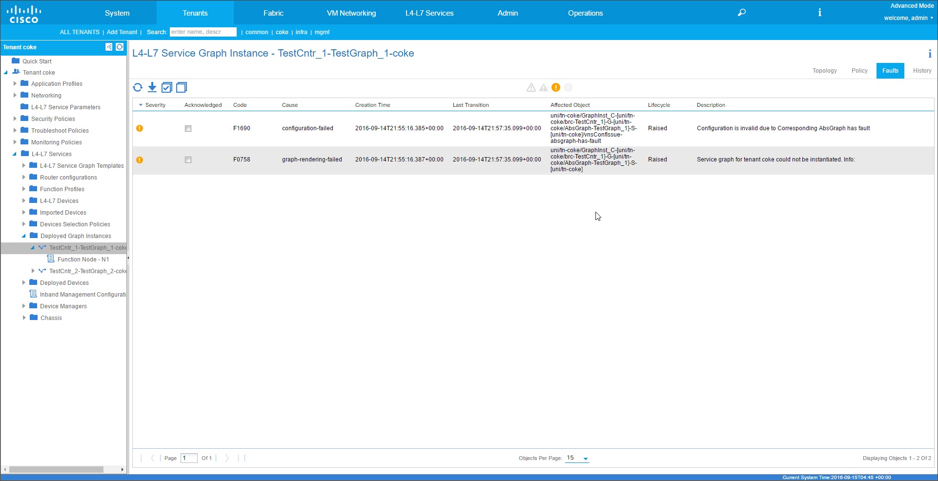
As part of the Service Graph deployment, the Hybrid Mode Device package pushes the configuration details from the Cisco APIC to the Citrix ADM. The Citrix ADM internally processes these configurations to the respective Citrix ADC and returns the response to the APIC. A successful graph deployment will have no fault, and the Citrix ADC is successfully networked with the fabric for the corresponding graph.
The APIC supports different ways to configure and deploy graphs by using APIs, and graph deployment includes various dependencies on some APIC-specific constructs, such as Tenant, contract, VLAN and namespace.
The following sample approach illustrates one of the ways to make use of the APIC’s APIs to create and deploy L4-L7 graphs, with the assumption that APIC specific artifacts are already configured in the APIC.
Important
Make sure that you use these XML payloads as a reference and make appropriate changes to the XML before you use them in your environment.
Following is an example of creating and deploying the service graph by using APIs:
-
Create AppProfile
-
Create service graph details
-
Attach the service graph to a contract
Following is a sample XML payload for creating an AppProfile. The AppProfile contains EPGs, and the provider EPG contains the Citrix ADC specific entities, attributes, and their values. In the following sample XML payload, Citrix ADC-specific network entities such as the NSIP are created with a set of attributes and StyleBook name.
<polUni>
    <fvTenant name="coke">
        <!-- Application Profile -->
        <fvAp dn="uni/tn-coke/ap-sap" name="sap">
            <!-- EPG 1  -->
            <fvAEPg dn="uni/tn-coke/ap-sap/epg-web" name="web">
                <fvRsBd tnFvBDName="BD_web" />
                <!-- --------- CONFIG PAYLOAD ---------------- -->
                <vnsFolderInst ctrctNameOrLbl="Ctrct1" graphNameOrLbl="Graph1" nodeNameOrLbl="ADC" key="Network" name="Network">
                    <vnsFolderInst ctrctNameOrLbl="Ctrct1" graphNameOrLbl="Graph1" nodeNameOrLbl="ADC" key="nsip" name="snip1">
                        <vnsParamInst key="ipaddress" name="ip1" value="110.110.110.2"/>
                        <vnsParamInst key="netmask" name="netmask1" value="255.255.255.0"/>
                        <vnsParamInst key="type" name="tye" value="SNIP"/>
                        <vnsParamInst key="dynamicrouting" name="dynamicrouting" value="DISABLED"/>
                        <vnsParamInst key="hostroute" name="hostroute" value="DISABLED"/>
                    </vnsFolderInst>
                    <vnsFolderInst ctrctNameOrLbl="Ctrct1" graphNameOrLbl="Graph1" nodeNameOrLbl="ADC" key="nsip" name="snip2">
                        <vnsParamInst key="ipaddress" name="ip2" value="220.220.220.2"/>
                        <vnsParamInst key="netmask" name="netmask2" value="255.255.255.0"/>
                        <vnsParamInst key="type" name="tye" value="SNIP"/>
                        <vnsParamInst key="dynamicrouting" name="dynamicrouting" value="DISABLED"/>
                        <vnsParamInst key="hostroute" name="hostroute" value="DISABLED"/>
                    </vnsFolderInst>
                </vnsFolderInst>
                <vnsFolderInst ctrctNameOrLbl="Ctrct1" graphNameOrLbl="Graph1" nodeNameOrLbl="ADC" key="Stylebook" name="stylebook_1">
                    <vnsParamInst name="stylebookName" key="name" value="APIC-HTTP-LB"/>
                </vnsFolderInst>
                <vnsFolderInst ctrctNameOrLbl="Ctrct1" graphNameOrLbl="Graph1" nodeNameOrLbl="ADC" key="internal_network" name="internal_network">
                    <vnsCfgRelInst name="internal_network_key" key="internal_network_key" targetName="Network/snip1"/>
                </vnsFolderInst>
                <vnsFolderInst ctrctNameOrLbl="Ctrct1" graphNameOrLbl="Graph1" nodeNameOrLbl="ADC" key="external_network" name="external_network">
                    <vnsCfgRelInst name="external_network_key" key="external_network_key" targetName="Network/snip2"/>
                </vnsFolderInst>
                <vnsFolderInst ctrctNameOrLbl="Ctrct1" graphNameOrLbl="Graph1" nodeNameOrLbl="ADC" key="mFCngStylebook" name="mFCngStylebook_1">
                    <vnsCfgRelInst name="Stylebook_key" key="Stylebook_key" targetName="stylebook_1"/>
                </vnsFolderInst>
                <!-- ------- END CONFIG PAYLOAD -------------- -->
                <fvSubnet ip="110.110.110.110/24" scope="shared"/>
                <fvRsProv tnVzBrCPName="Ctrct1"></fvRsProv>
                <fvRsDomAtt tDn="uni/phys-sepg" />
                <fvRsPathAtt tDn="topology/pod-1/paths-101/pathep-[eth1/38]" encap="vlan-3703" instrImedcy="immediate"/>
            </fvAEPg>
            <!-- EPG 2 -->
            <fvAEPg dn="uni/tn-coke/ap-sap/epg-app"  name="app">
                <fvRsCons tnVzBrCPName="Ctrct1"/>
                <fvRsBd tnFvBDName="BD_app" />
                <fvSubnet ip="220.220.220.220/24" scope="shared"/>
                <fvRsPathAtt tDn="topology/pod-1/paths-101/pathep-[eth1/37]" encap="vlan-3704" instrImedcy="immediate"/>
                <fvRsDomAtt tDn="uni/phys-sepg" />
            </fvAEPg>
        </fvAp>
    </fvTenant>
</polUni>
<!--NeedCopy-->
Following is a sample XML payload for creating service graph details:
<polUni>
    <fvTenant name="coke">
        <vnsAbsGraph name = "Graph1">
            <vnsAbsTermNodeProv name = "Input1">
                <vnsAbsTermConn name = "C1"></vnsAbsTermConn>
            </vnsAbsTermNodeProv>
            <vnsAbsNode name="ADC" funcType="GoTo">
                <vnsAbsFuncConn name = "outside" attNotify="true">
                    <vnsRsMConnAtt tDn="uni/infra/mDev-Citrix-NetScalerMAS-1.0/mFunc-ADCFunction/mConn-external" />
                </vnsAbsFuncConn>
                <vnsAbsFuncConn name = "inside" attNotify="true">
                    <vnsRsMConnAtt tDn="uni/infra/mDev-Citrix-NetScalerMAS-1.0/mFunc-ADCFunction/mConn-internal" />
                </vnsAbsFuncConn>
                <vnsRsNodeToMFunc tDn="uni/infra/mDev-Citrix-NetScalerMAS-1.0/mFunc-ADCFunction"/>
                <vnsRsDefaultScopeToTerm tDn="uni/tn-coke/AbsGraph-Graph1/AbsTermNodeProv-Input1/outtmnl"/>
                <vnsRsNodeToAbsFuncProf tDn="uni/infra/mDev-Citrix-NetScalerMAS-1.0/absFuncProfContr/absFuncProfGrp-ADCOneArmServiceProfileGroup/absFuncProf-A
DCOneArmFunctionProfile"/>
                <vnsRsNodeToLDev tDn="uni/tn-coke/lDevVip-ADCCluster1"/>
            </vnsAbsNode>
            <vnsAbsTermNodeCon name = "Output1">
                <vnsAbsTermConn name = "C6"></vnsAbsTermConn>
            </vnsAbsTermNodeCon>
            <vnsAbsConnection name = "CON1">
                <vnsRsAbsConnectionConns tDn="uni/tn-coke/AbsGraph-Graph1/AbsTermNodeCon-Output1/AbsTConn" />
                <vnsRsAbsConnectionConns tDn="uni/tn-coke/AbsGraph-Graph1/AbsNode-ADC/AbsFConn-outside" />
            </vnsAbsConnection>
            <vnsAbsConnection name = "CON2">
                <vnsRsAbsConnectionConns tDn="uni/tn-coke/AbsGraph-Graph1/AbsNode-ADC/AbsFConn-inside" />
                <vnsRsAbsConnectionConns tDn="uni/tn-coke/AbsGraph-Graph1/AbsTermNodeProv-Input1/AbsTConn" />
            </vnsAbsConnection>
        </vnsAbsGraph>
    </fvTenant>
</polUni>
<!--NeedCopy-->
Following is a sample XML payload for attaching the service graph to a contract:
<polUni> <fvTenant name="coke"> <vzBrCP name="Ctrct1"> <vzSubj name="http"> <vzRsSubjGraphAtt tnVnsAbsGraphName="Graph1"/> </vzSubj> </vzBrCP> </fvTenant> </polUni> <!--NeedCopy--> -
Share
Share
This Preview product documentation is Cloud Software Group Confidential.
You agree to hold this documentation confidential pursuant to the terms of your Cloud Software Group Beta/Tech Preview Agreement.
The development, release and timing of any features or functionality described in the Preview documentation remains at our sole discretion and are subject to change without notice or consultation.
The documentation is for informational purposes only and is not a commitment, promise or legal obligation to deliver any material, code or functionality and should not be relied upon in making Cloud Software Group product purchase decisions.
If you do not agree, select I DO NOT AGREE to exit.