GSLB overview and deployment topologies
Overview
For ensuring high availability, proximity-based load balancing, and scalability, you need to deploy an application in multiple distributed Kubernetes clusters. When an application is deployed in multiple Kubernetes clusters dispersed across geographically distributed locations, a load balancing decision has to be taken to distribute traffic among application instances.
NetScaler GSLB controller configures NetScaler (GSLB device) to load balance services among geographically distributed locations. GSLB solution ensures better performance and reliability for your Kubernetes services that are exposed using ingress or service type LoadBalancer. In the GSLB topology, a GSLB device is deployed in each region; one of the GSLB devices acts as the primary ADC and others act as the secondary ADCs. The GSLB primary ADC is configured by the GSLB controller deployed in each cluster deployed across sites. This GSLB device load balances services deployed in multiple clusters across sites.
For more information about GSLB, see Global Server Load Balancing.
Note:
The NetScaler GSLB controller image is the same as that of NetScaler Ingress Controller.
Deployment topologies
The components of GSLB deployment topology are described here:
- GSLB device: NetScaler MPX or NetScaler VPX is used as a global server load balancing (GSLB) device. A GSLB device is configured for each data center. In each GSLB device, one site is configured as a local site representing the local data center. The other sites are configured as remote sites. NetScaler MPX or NetScaler VPX used as the GSLB device can also be used as the ingress device with NetScaler Ingress Controller.
- Ingress load balancer: NetScaler CPX or any third-party application is deployed as the ingress load balancer in each Kubernetes cluster.
- Ingress controller: The ingress controller can be a NetScaler Ingress Controller or any third-party ingress controller.
- GSLB controller: Each cluster in the deployment runs a GSLB controller instance. Each GSLB controller configures the GSLB primary ADC for the applications deployed in its respective cluster. The global server load balancing (GSLB) configuration synchronization option is used to copy the GSLB configuration on the primary site to all the GSLB sites in the GSLB setup. The NetScaler on which you configure GSLB synchronization is referred as the primary site and the sites to which the configuration is copied are referred as the secondary sites.
The following deployment diagrams show sample topologies for NetScaler GSLB controller. Each sample topology contains two data centers (sites) in different regions and each data center contains a Kubernetes cluster.
Let’s consider two sample deployment topologies based on the type of ingress controller used in the GSLB sites:
- NetScaler® Ingress Controller in both GSLB sites
- Any third-party ingress controller in both GSLB sites
Note:
GSLB controller deployment is also supported with NetScaler Ingress Controller in one GSLB site and a third-party ingress controller in another GSLB site.
NetScaler Ingress Controller in both GSLB sites
Note:
NetScaler MPX or NetScaler VPX used for GSLB and ingress or service type LoadBalancer can be the same or different. In the following example, the same is used for GSLB and ingress or service type LoadBalancer.
The following diagram explains the deployment topology for NetScaler GSLB controller in presence of NetScaler Ingress Controller.
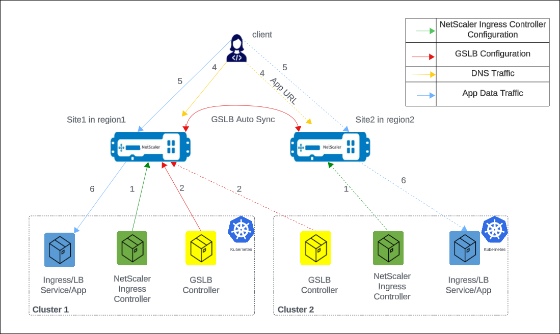
The numbers in the following steps map to the numbers in the earlier diagram.
-
In each cluster, NetScaler Ingress Controller configures NetScaler either using
ingressor using theservice of type LoadBalancerconfiguration. -
In each cluster, NetScaler GSLB controller configures the GSLB device in the primary site with the GSLB configuration.
-
GSLB configuration synchronizes automatically between the GSLB devices in different GSLB sites.
-
A DNS query for application host name or FQDN is sent to the GSLB virtual server configured on NetScaler. The DNS resolution on the GSLB virtual server resolves to an IP address on any one of the clusters based on the configured global traffic policy (GTP).
-
Based on the DNS resolution, data traffic lands on either the Ingress front-end IP address or service type LoadBalancer IP address of one of the clusters.
-
The required application is accessed through the GSLB device.
Any third-party ingress controller in both GSLB sites
The following diagram explains the deployment topology for NetScaler GSLB controller in the presence of any third-party ingress controller.
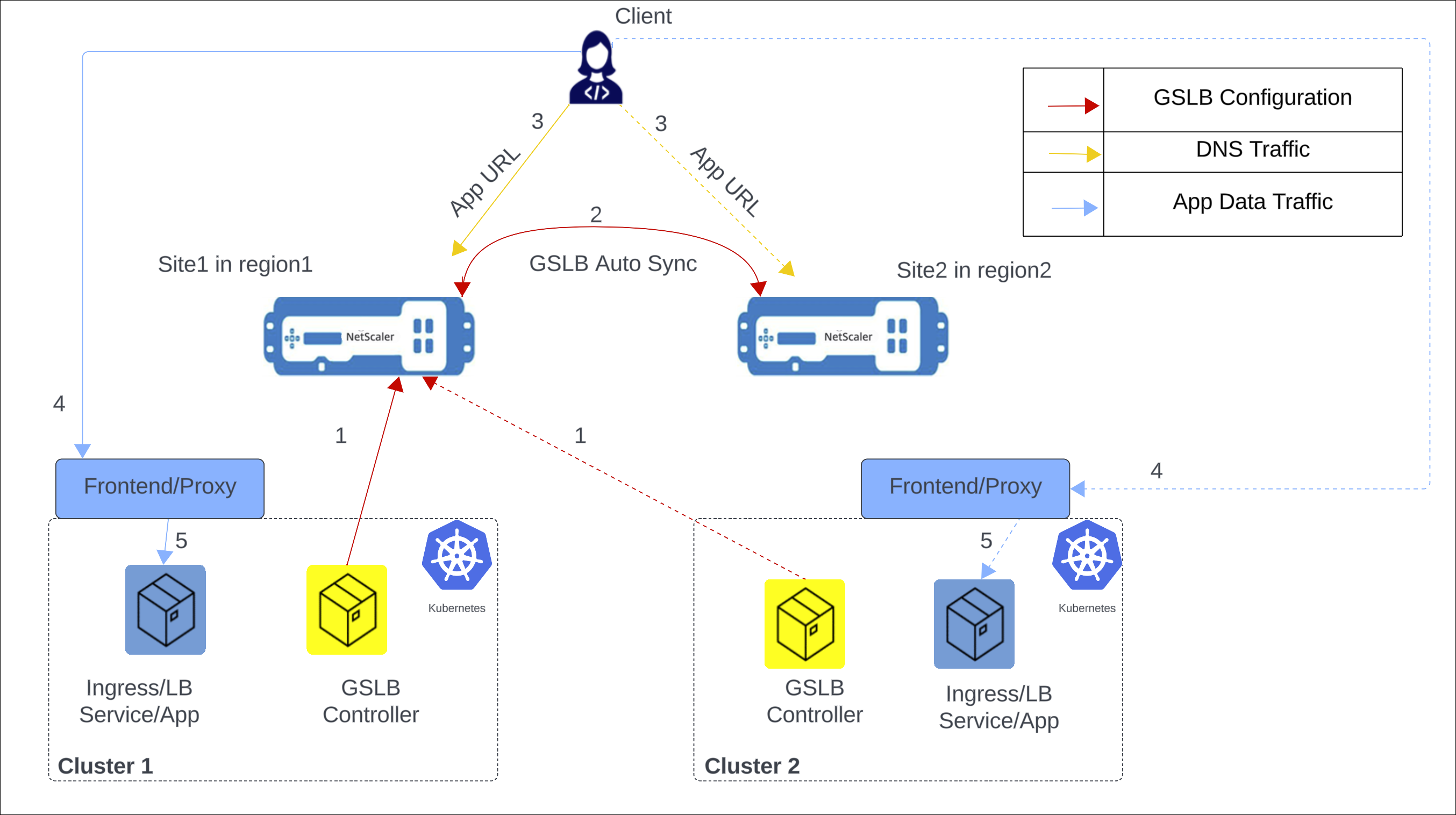
The following items explain the previous diagram:
-
NetScaler GSLB controller configures the GSLB primary ADC in the primary site with the GSLB configuration.
-
GSLB configuration synchronizes automatically between the GSLB devices in different GSLB sites.
-
A DNS query for application hostname or FQDN is sent to the GSLB virtual server configured on NetScaler. The DNS resolution on the GSLB virtual server resolves to an IP address on any one of the clusters based on the configured global traffic policy (GTP).
-
Based on the DNS resolution, data traffic lands on either the ingress front-end IP address or service type LoadBalancer front-end IP address of one of the clusters.
-
The required application is accessed through proxy.
GSLB methods and supported deployment types
The following global load balancing methods are supported:
The following deployment types are supported:
-
Local first: In a local first deployment, when an application wants to communicate with another application, it prefers a local application in the same cluster. When the application is not available locally, the request is directed to other clusters or regions.
-
Canary: Canary release is a technique to reduce the risk of introducing a new software version in production by first rolling out the change to a small subset of users. In this solution, canary deployment can be used when you want to roll out new versions of the application to selected clusters before moving it to production.
-
Failover: A failover deployment is used when you want to deploy applications in an active/passive configuration when they cannot be deployed in active/active mode.
-
Round trip time (RTT): In an RTT deployment, the real-time status of the network is monitored and dynamically directs the client request to the data center with the lowest RTT value.
-
Static proximity: In a static proximity deployment, an IP-address based static proximity database is used to determine the proximity between the client’s local DNS server and the GSLB sites. The requests are sent to the site that best matches the proximity criteria.
-
Round robin: In a round robin deployment, the GSLB device continuously rotates a list of the services that are bound to it. When it receives a request, it assigns the connection to the first service in the list, and then moves that service to the bottom of the list.
Note:
Currently, IPv6 is not supported.
CRDs for configuring NetScaler GSLB controller for applications deployed in distributed Kubernetes clusters
The following CRDs are introduced to support NetScaler configuration for performing GSLB of Kubernetes applications.
- Global traffic policy (GTP)
- Global service entry (GSE)
GTP CRD
GTP CRD accepts the parameters for configuring GSLB on NetScaler including deployment type (canary, failover), GSLB domain, health monitor for the ingress, and service type.
The GTP CRD spec is available at https://github.com/netscaler/netscaler-k8s-ingress-controller/blob/master/gslb/Manifest/gtp-crd.yaml.
Note:
GTP CRD is the same across all the clusters for a given domain.
The following table explains the GTP CRD attributes.
| Field | Description |
|---|---|
ipType |
Specifies the DNS record type as A or AAAA. Currently, only A record type is supported |
serviceType |
Specifies the protocol to which GSLB support is applied. |
host |
Specifies the domain for which GSLB support is applied. |
trafficPolicy |
Specifies the traffic distribution policy supported in a GSLB deployment. |
sourceIpPersistenceId |
Specifies the unique source IP persistence ID. This attribute enables persistence based on the source IP address for the inbound packets. The sourceIpPersistenceId attribute should be a multiple of 100 and should be unique. |
secLbMethod |
Specifies the traffic distribution policy supported among clusters under a group in local-first, canary, or failover. |
destination |
Specifies the Ingress or LoadBalancer service endpoint in each cluster. The destination name should match with the name of GSE. |
weight |
Specifies the proportion of traffic to be distributed across clusters. For canary deployment, the proportion is specified as percentage. |
CIDR |
Specifies the CIDR to be used in local-first to determine the scope of the locality. |
primary |
Specifies whether the destination is a primary cluster or a backup cluster in the failover deployment. |
monType |
Specifies the type of probe to determine the health of the GSLB endpoint. When the monitor type is HTTPS, SNI is enabled by default during the TLS handshake. |
uri |
Specifies the path to be probed for the health of the GSLB endpoint for HTTP and HTTPS protocols. |
respCode |
Specifies the response code expected to mark the GSLB endpoint as healthy for HTTP and HTTPS protocols. |
customHeader |
Specifies the custom header that you want to add to the GSLB-endpoint monitoring traffic. |
GSE CRD
GSE CRD dictates the endpoint information (any Kubernetes object which routes traffic into the cluster) in each cluster.
The GSE CRD spec is available in the NetScaler Ingress Controller GitHub repo at: gse-crd.yaml.
The following table explains the GSE CRD attributes.
| Field | Description |
|---|---|
| ipv4address | Local cluster ingress ipv4 address or service of type LoadBalancer endpoint ipv4 address |
| domainName | Local cluster ingress domain name or service of type LoadBalancer domain name |
| monitorPort | Listening port of local cluster ingress or Listening port of service of type LoadBalancer
|
Note:
- The GSE CRD is cluster-specific, and a separate GSE CRD is created for each cluster.
- For auto-generation of GSE CRD with Ingress, the host name must match the host name specified in the GTP CRD instance.
- For both Ingress and Service of type
LoadBalancer, the GSE CRD is generated only for the first port specified.- The GSE CRD is auto-generated only when the corresponding Service or Ingress has the
status.loadBalancer.ingress.ip/hostnamefield populated.
ConfigMap for configuring local site preference
When configuring GSLB devices, it’s important to select the virtual IP addresses and applications deployed in the Kubernetes or OpenShift Cluster that is geographically closest to the ADNS IP address for efficient traffic routing and minimized latency.
You can use the local site preference configuration for GSLB devices to resolve to the local virtual IP address if the services are available. You can achieve this scenario by setting the priority order for GSLB services using load balancing policy commands. For more information, see Configure priority order for GSLB services using load balancing policy commands.
The priority order for services or service groups within GSLB devices enables effective network traffic management and optimization. It is typically configured when binding a service group to a GSLB virtual server. Prioritizing specific services or groups ensures that critical applications are given preference during load balancing, especially when demand is high or low-latency connections are required.
The localSiteSelection parameter is added to the Netscaler-gslb-controller Helm chart to enable local site preference. Setting this parameter to true automatically adds the configuration to the GSLB device. The parameter creates a ConfigMap for the GSLB controller, which supports on-the-fly addition, modification, and deletion of the configuration.
Note:
- For any configuration (addition or modification or deletion) for local site preference through the ConfigMap, traffic gets affected as priority order for service groups must be configured or unconfigured.
- The ConfigMap must be configured in all clusters.
Sample local site priority configuration for the GSLB devices:
add lb action <site1-act> -type SELECTIONORDER -value 1 2 3
add lb action <site2-act> -type SELECTIONORDER -value 2 3 1
add lb action <site3-act> -type SELECTIONORDER -value 3 1 2
add lb policy <site1-pol> -rule "CLIENT.IP.DST.EQ<site1_ip>" -action <site1-act>
add lb policy <site2-pol> -rule "CLIENT.IP.DST.EQ<site2_ip>" -action <site2-act>
add lb policy <site3-pol> -rule "CLIENT.IP.DST.EQ<site3_ip>" -action <site3-act>
bind gslb vserver <gslb_name> -serviceGroupName <sg_name_1> -order 1
bind gslb vserver <gslb_name> -serviceGroupName <sg_name_2> -order 2
bind gslb vserver <gslb_name> -serviceGroupName <sg_name_3> -order 3
bind gslb vserver <gslb_name> -policyName <site1-pol> -priority 1
bind gslb vserver <gslb_name> -policyName <site2-pol> -priority 2
bind gslb vserver <gslb_name> -policyName <site3-pol> -priority 3
<!--NeedCopy-->
For configuring ConfigMap using the Helm chart, see https://github.com/netscaler/netscaler-helm-charts/tree/master/netscaler-gslb-controller.
For configuring ConfigMap using the OpenShift operator, see https://docs.netscaler.com/en-us/netscaler-k8s-ingress-controller/deploy/gslb-openshift-operator.