NetScaler® GSLB controller for single site
Overview
For ensuring high availability, proximity-based load balancing, and scalability, you need to deploy an application in multiple Kubernetes clusters. GSLB solution ensures better performance and reliability for your Kubernetes services that are exposed using Ingress. NetScaler GSLB controller configures NetScaler (GSLB device) to load balance services among geographically distributed locations. In a single-site GSLB solution, a GSLB device in a data center is configured by the GSLB controller deployed in each Kubernetes cluster of a data center. This GSLB device load balances services deployed in multiple clusters of the data center.
The following diagram describes the deployment topology for NetScaler GSLB controller in a data center with two Kubernetes clusters and a single GSLB site.
Note:
The NetScaler (MPX or VPX) used for GSLB and Ingress can be the same or different. In the following diagram, the same NetScaler is used for GSLB and Ingress.
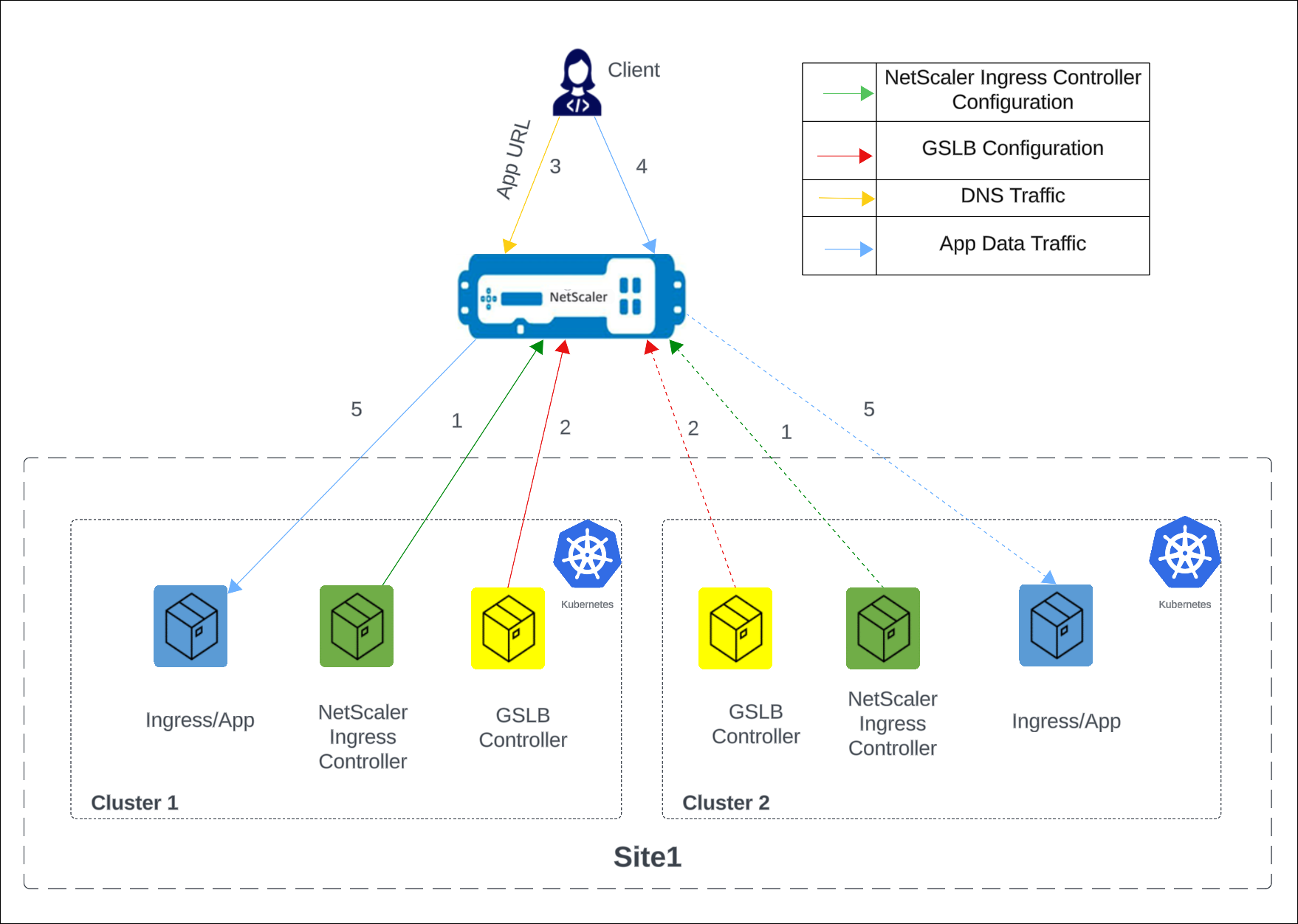
The numbers in the following steps map to the numbers in the earlier diagram.
-
In each cluster, the NetScaler Ingress Controller configures NetScaler using
Ingress. -
In each cluster, the NetScaler GSLB controller configures the GSLB device with the GSLB configuration.
-
A DNS query for the application URL is sent to the GSLB virtual server configured on NetScaler. The DNS resolution on the GSLB virtual server resolves to an IP address on any one of the clusters based on the configured global traffic policy (GTP).
-
Based on the DNS resolution, data traffic lands on either the Ingress front-end IP address or the content switching virtual server IP address of one of the clusters.
-
The required application is accessed through the GSLB device.
Deploy NetScaler GSLB controller
Prerequisites
- Access to Kubernetes clusters hosted in cloud or on-premises. The Kubernetes cluster in the cloud can be a managed Kubernetes (for example: GKE, EKS, or AKS) or a custom created Kubernetes deployment. Kubernetes clusters must be properly configured and operational. Ensure the network connectivity between NetScaler and the cluster’s pod network.
- For Kubernetes deployment, you need access to Kubernetes clusters running version 1.21 or later.
- For OpenShift deployment, you need access to OpenShift clusters running version 4.11 or later.
- You have installed Helm version 3.x or later. To install Helm, see here.
- NetScaler MPX/VPX is deployed in a standalone, HA, or cluster setup depending on your specific needs.
- For instructions to deploy NetScaler MPX, see NetScaler documentation.
- For instructions to deploy NetScaler VPX, see Deploy a NetScaler VPX instance.
- Determine the NSIP (NetScaler IP) address using which NetScaler Ingress Controller communicates with NetScaler. The IP address might be any one of the following IP addresses depending on the type of NetScaler deployment:
-
NSIP (for standalone appliances) - The management IP address of a standalone NetScaler appliance. For more information, see IP Addressing in NetScaler.
-
SNIP (for appliances in High Availability mode) - The subnet IP address. For more information, see IP Addressing in NetScaler.
-
CLIP (for appliances in Cluster mode) - The cluster management IP (CLIP) address for a cluster NetScaler deployment. For more information, see IP addressing for a cluster.
-
-
A user account in NetScaler VPX or NetScaler MPX. NetScaler Ingress Controller uses a system user account in NetScaler to configure NetScaler MPX or NetScaler VPX. For instructions to create the system user account on NetScaler, see Create System User Account for NetScaler Ingress Controller in NetScaler.
You can directly pass the user name and password or use Kubernetes secrets. If you want to use Kubernetes secrets, create a secret for the user name and password using the following command:
   kubectl create secret generic nslogin --from-literal=username=<username> --from-literal=password=<password>
   <!--NeedCopy-->
Steps to deploy GSLB controller for a single site
In this procedure, we deploy the same HTTPS application in two clusters of a site, deploy the GSLB controller in each cluster such that the GSLB controllers configure the GSLB device (NetScaler VPX or NetScaler MPX) to load balance services deployed across the clusters.
Note:
- Repeat the following steps in both the clusters to set up a single-site GSLB solution. There are exceptions added in some steps highlighting what must be done in a particular cluster; perform the steps accordingly.
- You must deploy ingressed resources in the application namespace.
- You must deploy GTP and GSE resources in the same namespace. We recommend you to deploy these resources in the application namespace.
-
Create a certificate-key pair with
cnn.comas the common name in the certificate signing request (CSR) in NetScaler VPX or NetScaler MPX. For information about creating a certificate-key pair, see Create a certificate. -
Deploy the CNN application using the following command.
kubectl apply -f - <<EOF
apiVersion: apps/v1
kind: Deployment
metadata:
  name: cnn-website
  labels:
    name: cnn-website
    app: cnn-website
spec:
  selector:
    matchLabels:
      app: cnn-website
  replicas: 2
  template:
    metadata:
      labels:
        name: cnn-website
        app: cnn-website
    spec:
      containers:
      - name: cnn-website
        image: quay.io/sample-apps/cnn-website:v1.0.0
        ports:
        - name: http-80
          containerPort: 80
        - name: https-443
          containerPort: 443
---
apiVersion: v1
kind: Service
metadata:
  name: cnn-website
  labels:
    app: cnn-website
spec:
  type: NodePort
  ports:
  - name: http-80
    port: 80
    targetPort: 80
  - name: https-443
    port: 443
    targetPort: 443
  selector:
    name: cnn-website
EOF
  <!--NeedCopy-->
Note:
For an OpenShift deployment, run the following command
oc adm policy add-scc-to-user anyuid system:serviceaccount:<namespace>:defaultto grant a specific Security Context Constraint (SCC) to a service account. Replace<namespace>with the actual namespace where you have deployed the CNN application. -
Deploy NSIC.
-
Add the NetScaler Helm chart repository to your local Helm registry using the following command:
helm repo add netscaler https://netscaler.github.io/netscaler-helm-charts/
<!--NeedCopy-->
If the NetScaler Helm chart repository is already added to your local registry, use the following command to update the repository:
helm repo update netscaler <!--NeedCopy--> -
Update
values.yamlto configure NetScaler Ingress Controller as described as following.Example
values.yamlfor cluster1license: accept: yes adcCredentialSecret: nslogin # K8s Secret created as part of prerequisiste nsIP: <x.x.x> # CLIP (for appliances in Cluster mode), SNIP (for appliances in High Availability mode) , NSIP (for standalone appliances) openshift: false # set to true for OpenShift deployments entityPrefix: cluster1 # unique for each NSIC instance. clusterName: cluster1 ingressClass: ['nsic-vpx'] # ingress class used in the ingress resources # serviceClass- To use service type LB, specify the service class <!--NeedCopy-->Example
values.yamlfor cluster2license: accept: yes adcCredentialSecret: nslogin # K8s Secret created as part of prerequisiste nsIP: <x.x.x> # CLIP (for appliances in Cluster mode), SNIP (for appliances in High Availability mode) , NSIP (for standalone appliances) openshift: false # set to true for OpenShift deployments entityPrefix: cluster2 # unique for each NSIC instance. clusterName: cluster2 ingressClass: ['nsic-vpx'] # ingress class used in the ingress resources # serviceClass- To use service type LB, specify the service class <!--NeedCopy--> -
Install NSIC using the Helm chart by running the following command.
helm install nsic netscaler/netscaler-ingress-controller -f values.yaml
<!--NeedCopy-->
For information about the mandatory and optional parameters that you can configure during NSIC installation, see Configuration.
Note:
If an earlier version of NSIC is already deployed in the cluster, deploy the CRD specification using the following command:
kubectl apply -f https://raw.githubusercontent.com/netscaler/netscaler-helm-charts/refs/heads/master/netscaler-ingress-controller/crds/crds.yaml.
-
-
Deploy the following ingress resource.
Ingress resource in cluster1.
kubectl apply -f - <<EOF
apiVersion: networking.k8s.io/v1
kind: Ingress
metadata:
  name: frontend-ingress
  annotations:
    ingress.citrix.com/frontend-ip: <NSVIP1> # vserver IP1
    ingress.citrix.com/preconfigured-certkey: '{"certs": [{"name": "singlesite", "type": "default"}]}' # provide the certificate key created in step 1
spec:
  tls:
  - {}
  ingressClassName: nsic-vpx
  rules:
    - host: cnn.com
      http:
        paths:
          - path: /
            pathType: Prefix
            backend:
              service:
                name: cnn-website
                port:
                  number: 80
EOF
<!--NeedCopy-->
Ingress resource in cluster2.
kubectl apply -f - <<EOF apiVersion: networking.k8s.io/v1 kind: Ingress metadata: name: frontend-ingress annotations: ingress.citrix.com/frontend-ip: <NSVIP2> # vserver IP2 ingress.citrix.com/preconfigured-certkey: '{"certs": [{"name": "singlesite", "type": "default"}]}' # provide the name of the certificate key created in step 1 spec: tls: - {} ingressClassName: nsic-vpx rules: - host: cnn.com http: paths: - path: / pathType: Prefix backend: service: name: cnn-website port: number: 80 EOF <!--NeedCopy--> -
Create the secrets required for the GSLB controller to connect to GSLB devices and push the configuration from the GSLB controller.
kubectl create secret generic secret--from-literal=username=<username for gslb device>--from-literal=password=<password for gslb device>
<!--NeedCopy-->
Note:
- This secret is provided as a parameter in the GSLB controller
helm installcommand for the respective sites. Specify the credentials of a NetScaler (GSLB device) user asusernameandpasswordin the command. - In this case, because the GSLB device and the ingress device are the same, you can use the same secret that is created in the prerequisites section.
- This secret is provided as a parameter in the GSLB controller
-
Install GSLB controller using the Helm chart by running the following command.
  helm install my-release netscaler/netscaler-gslb-controller -f values.yaml
  <!--NeedCopy-->
Note:
The chart installs the recommended RBAC roles and role bindings by default.
Example
values.yamlfile:license: accept: yes localRegion: "east" localCluster: "cluster1" # use cluster2 when deploying GSLB controller in cluster2 entityPrefix: "gslb" # should be same for GSLB controller in both clusters nsIP: "x.x.x.x" openshift: false # set to true for OpenShift deployments adcCredentialSecret: <Secret-for-NetScaler-credentials> sitedata: - siteName: "site1" siteIp: "x.x.x.x" siteMask: sitePublicip: secretName: "secret" siteRegion: "east" <!--NeedCopy-->Specify the following parameters in the YAML file.
Parameter Description LocalRegion Local region where the GSLB controller is deployed. This value is the same for GSLB controller deployment across all the clusters. LocalCluster The name of the cluster in which the GSLB controller is deployed. This value is unique for each Kubernetes cluster. sitedata[0].siteName The name of the GSLB site. sitedata[0].siteIp IP address for the GSLB site. Add the IP address of the NetScaler in site 1 as sitedata[0].siteIp. sitedata[0].siteMask The netmask of the GSLB site IP address. sitedata[0].sitePublicIp The site public IP address of the GSLB site. sitedata[0].secretName The name of the secret that contains the login credentials of the GSLB site. sitedata[0].siteRegion The region of the GSLB site. NSIP The SNIP (subnet IP address) of the GSLB device. Add the sitedata[0].siteIp as SNIP on NetScaler. adcCredentialSecret The Kubernetes secret containing the login credentials for NetScaler VPX or MPX. After the successful installation of a GSLB controller on each cluster, GSLB site and ADNS service are configured and management access is enabled on the GSLB site IP address.
Note:
If an earlier version of GSLB controller is already deployed in the cluster, deploy the GTP and GSE CRD specifications using the following commands:
kubectl apply -f https://raw.githubusercontent.com/netscaler/netscaler-k8s-ingress-controller/master/gslb/Manifest/gtp-crd.yamlandkubectl apply -f https://raw.githubusercontent.com/netscaler/netscaler-k8s-ingress-controller/master/gslb/Manifest/gse-crd.yaml. -
Deploy a Global traffic policy based on your requirement.
Notes:
- Ensure that the GTP configuration is the same across all the clusters. For information on GTP CRD and allowed values, see GTP CRD.
- The destination information in the GTP YAML must be in the format
servicename.namespace.region.cluster, where the service name and namespace correspond to the Kubernetes object of type Service and its namespace, respectively.
You can specify the load balancing method for canary and failover deployments.
-
Example 1: Round robin deployment
Use this deployment to distribute the traffic evenly across the clusters. The following example configures a GTP for round robin deployment. You can use the
weightfield to direct more client requests to a specific cluster within a group.kubectl apply -f - <<EOF apiVersion: "citrix.com/v1beta1" kind: globaltrafficpolicy metadata: name: gtp1 spec: serviceType: 'HTTP' hosts: - host: 'cnn.com' policy: trafficPolicy: 'ROUNDROBIN' targets: - destination: 'cnn-website.default.east.cluster1' weight: 2 - destination: 'cnn-website.default.east.cluster2' weight: 5 monitor: - monType: http uri: '' respCode: 200 EOF <!--NeedCopy--> -
Example 2: Failover deployment
Use this policy to configure the application in active-passive mode. In a failover deployment, the application is deployed in multiple clusters. Failover is achieved between the instances in target destinations based on the weight assigned to those target destinations in the GTP policy.
The following example shows a sample GTP configuration for failover. Using the
primaryfield, you can specify which target destination is active and which target destination is passive. The default value for theprimaryfield isTrueindicating that the target destination is active. Bind a monitor to the endpoints in each cluster to probe their health.kubectl apply -f - <<EOF apiVersion: "citrix.com/v1beta1" kind: globaltrafficpolicy metadata: name: gtp1 spec: serviceType: 'HTTP' hosts: - host: 'cnn.com' policy: trafficPolicy: 'FAILOVER' secLbMethod: 'ROUNDROBIN' targets: - destination: 'cnn-website.default.east.cluster1' weight: 1 - destination: 'cnn-website.default.east.cluster2' primary: false weight: 1 monitor: - monType: http uri: '' respCode: 200 EOF <!--NeedCopy-->-
Example 3: RTT deployment
Use this policy to monitor the real-time status of the network and dynamically direct the client request to the target destination with the lowest RTT value.
The following example configures a GTP for RTT deployment.
kubectl apply -f - <<EOF apiVersion: "citrix.com/v1beta1" kind: globaltrafficpolicy metadata: name: gtp1 spec: serviceType: 'HTTP' hosts: - host: 'cnn.com' policy: trafficPolicy: 'RTT' targets: - destination: 'cnn-website.default.east.cluster1' - destination: 'cnn-website.default.east.cluster2' monitor: - monType: http uri: '' respCode: 200 EOF <!--NeedCopy--> -
Example 4: Canary deployment
Use the canary deployment when you want to roll out new versions of the application to selected clusters before moving it to production.
This section describes a sample global traffic policy with Canary deployment, where you need to roll out a newer version of an application in stages before deploying it in production.
In this example, a stable version of an application is deployed in
cluster2. A new version of the application is deployed incluster1. Using theweightfield, specify how much traffic is redirected to each cluster. Here,weightis specified as 40 percent. Hence, only 40 percent of the traffic is directed to the new version. If theweightfield is not mentioned for a destination, it is considered as part of the production which takes the majority traffic. When the newer version of the application is stable, the new version can be rolled out to the other clusters.kubectl apply -f - <<EOF apiVersion: "citrix.com/v1beta1" kind: globaltrafficpolicy metadata: name: gtp1 namespace: default spec: serviceType: 'HTTP' hosts: - host: 'cnn.com' policy: trafficPolicy: 'CANARY' secLbMethod: 'ROUNDROBIN' targets: - destination: 'cnn-website.default.east.cluster1' weight: 40 - destination: 'cnn-website.default.east.cluster2' monitor: - monType: http uri: '' respCode: 200 EOF <!--NeedCopy--> -
Example 5: Static proximity
Use this policy to select the service that best matches the proximity criteria. The following traffic policy is an example for static proximity deployment.
Note:
For static proximity, you must apply the location database manually:
add locationfile /var/netscaler/inbuilt_db/Citrix_Netscaler_InBuilt_GeoIP_DB_IPv4.kubectl apply -f - <<EOF apiVersion: "citrix.com/v1beta1" kind: globaltrafficpolicy metadata: name: gtp1 namespace: default spec: serviceType: 'HTTP' hosts: - host: 'cnn.com' policy: trafficPolicy: 'STATICPROXIMITY' targets: - destination: 'cnn-website.default.east.cluster1' - destination: 'cnn-website.default.east.cluster2' monitor: - monType: http uri: '' respCode: 200 EOF <!--NeedCopy-->- Example 6: Source IP persistence
The following traffic policy is an example to enable source IP persistence by providing the parameter
sourceIpPersistenceId.kubectl apply -f - <<EOF apiVersion: "citrix.com/v1beta1" kind: globaltrafficpolicy metadata: name: gtp1 namespace: default spec: serviceType: 'HTTP' hosts: - host: 'cnn.com' policy: trafficPolicy: 'ROUNDROBIN' sourceIpPersistenceId: 300 targets: - destination: 'cnn-website.default.east.cluster1' weight: 2 - destination: 'cnn-website.default.east.cluster2' weight: 5 monitor: - monType: http uri: '' respCode: 200 EOF <!--NeedCopy--> -
Deploy the GSE resource.
GSE configuration is applied in a specific cluster based on the cluster endpoint information. The GSE name must be the same as the target destination name in the global traffic policy.
Note:
Creating a GSE is optional. If GSE is not created, NetScaler Ingress Controller looks for matching ingress with host matching
<svcname>.<namespace>.<region>.<cluster>format.For a global traffic policy mentioned in the earlier examples, the following YAML is the global service entry for cluster1. In this example, the global service entry name
cnn.default.east.cluster1is one of the target destination names in the global traffic policy.kubectl apply -f - <<EOF apiVersion: "citrix.com/v1beta1" kind: globalserviceentry metadata: name: 'cnn-website.default.east.cluster1' spec: endpoint: ipv4address: NSVIP1 # vserver IP1 monitorPort: 80 EOF <!--NeedCopy-->For a global traffic policy mentioned in the earlier examples, the following YAML is the global service entry for cluster2. In this example, the global service entry name
cnn.default.east.cluster2is one of the target destination names in the global traffic policy.kubectl apply -f - <<EOF apiVersion: "citrix.com/v1beta1" kind: globalserviceentry metadata: name: 'cnn-website.default.east.cluster2' spec: endpoint: ipv4address: NSVIP2 # vserver IP2 monitorPort: 80 EOF <!--NeedCopy--> -
To send a DNS query, use the following command.
dig@siteIP cnn.com
<!--NeedCopy-->