Multi-cloud and GSLB solution with Amazon EKS and Microsoft AKS clusters
You can deploy multiple instances of the same application across multiple clouds provided by different cloud providers. This multi-cloud strategy helps you to ensure resiliency, high availability, and proximity. A multi-cloud approach also allows you to take advantage of the best of each cloud provider by reducing the risks such as vendor lock-in and cloud outages.
NetScaler with the help of the NetScaler Ingress Controller can perform multi-cloud load balancing. NetScaler can direct traffic to clusters hosted on different cloud provider sites. The solution performs load balancing by distributing the traffic intelligently between the workloads running on Amazon EKS (Elastic Kubernetes Service) and Microsoft AKS (Azure Kubernetes Service) clusters.
You can deploy the multi-cloud and GSLB solution with Amazon EKS and Microsoft AKS.
Deployment topology
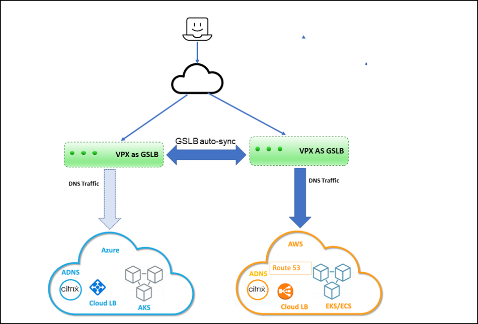
The following diagram explains a deployment topology of the multi-cloud ingress and load balancing solution for Kubernetes service provided by Amazon EKS and Microsoft AKS.

Prerequisites
- You should be familiar with AWS and Azure.
- You should be familiar with NetScaler and NetScaler networking.
- Instances of the same application must be deployed in Kubernetes clusters on Amazon EKS and Microsoft AKS.
To deploy the multi-cloud and GSLB solution, you must perform the following tasks.
- Deploy NetScaler VPX in AWS.
- Deploy NetScaler VPX in Azure.
- Configure ADNS service on NetScaler VPX deployed in AWS and AKS.
- Configure GSLB service on NetScaler VPX deployed in AWS and AKS.
- Apply GTP and GSE CRDs on AWS and Azure Kubernetes clusters.
- Deploy the GSLB controller.
Deploying NetScaler VPX in AWS
You must ensure that the NetScaler VPX instances are installed in the same virtual private cloud (VPC) on the EKS cluster. It enables NetScaler VPX to communicate with EKS workloads. You can use an existing EKS subnet or create a subnet to install the NetScaler VPX instances.
Also, you can install the NetScaler VPX instances in a different VPC. In that case, you must ensure that the VPC for EKS can communicate using VPC peering. For more information about VPC peering, see VPC peering documentation.
For high availability (HA), you can install two instances of NetScaler VPX in HA mode.
-
Install NetScaler VPX in AWS. For information on installing NetScaler VPX in AWS, see Deploy NetScaler VPX instance on AWS.
NetScaler VPX requires a secondary public IP address other than the NSIP to run GSLB service sync and ADNS service.
-
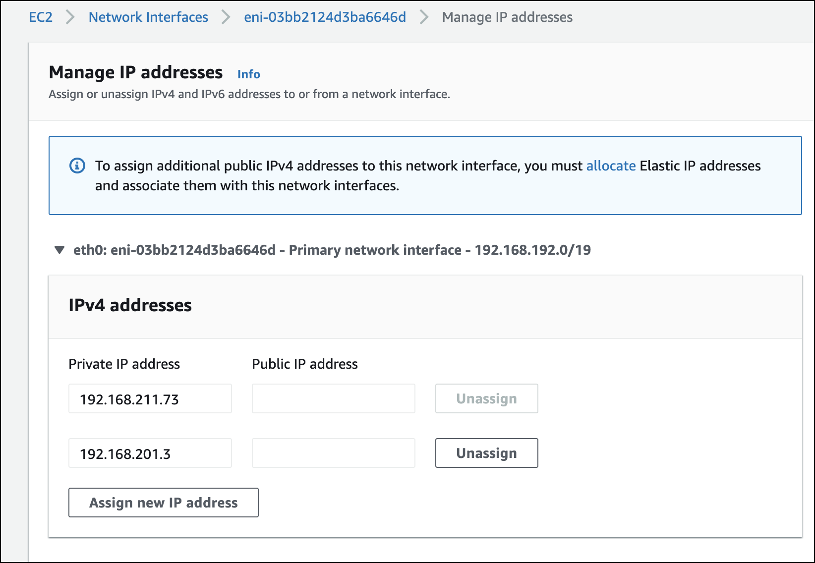
Open the AWS console and choose EC2 > Network Interfaces > VPX primary ENI ID > Manage IP addresses. Click Assign new IP Address.

After the secondary public IP address has been assigned to the VPX ENI, associate an elastic IP address to it.
-
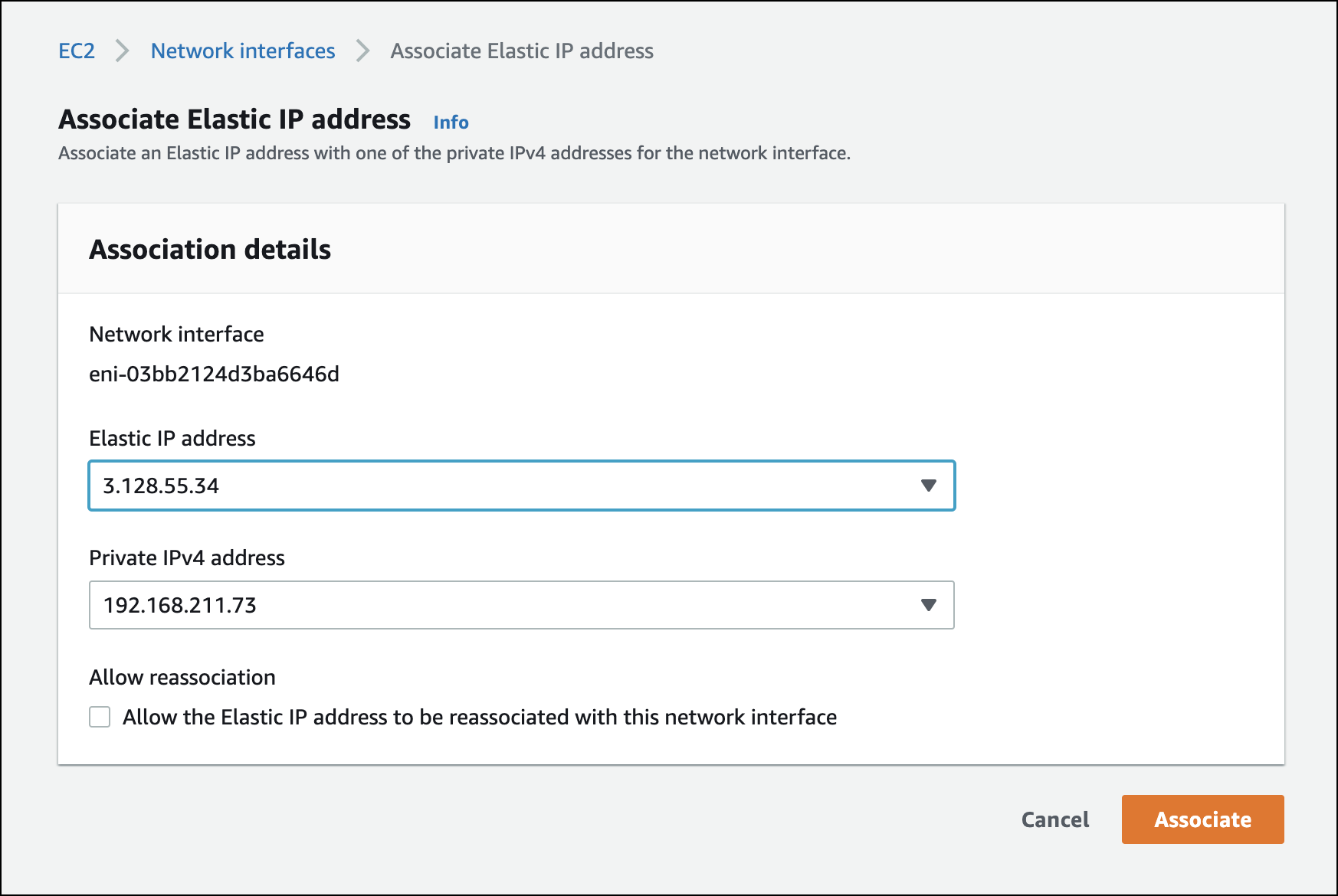
Choose EC2 > Network Interfaces > VPX ENI ID - Actions , click Associate IP Address. Select an elastic IP address for the secondary IP address and click Associate.

-
Log in to the NetScaler VPX instance and add the secondary IP address as
SNIPand enable the management access using the following command:add ip 192.168.211.73 255.255.224.0 -mgmtAccess ENABLED -type SNIPNote:
-
To log in to NetScaler VPX using SSH, you must enable the SSH port in the security group. Route tables must have an internet gateway configured for the default traffic and the NACL must allow the SSH port.
-
If you are running the NetScaler VPX in High Availability (HA) mode, you must perform this configuration in both of the NetScaler VPX instances.
-
-
Enable Content Switching (CS), Load Balancing (LB), Global Server Load Balancing(GSLB), and SSL features in NetScaler VPX using the following command:
enable feature *feature*Note:
To enable GSLB, you must have an additional license.
-
Enable port 53 for UDP and TCP in the VPX security group for NetScaler VPX to receive DNS traffic. Also enable the TCP port 22 for SSH and the TCP port range 3008–3011 for GSLB metric exchange.
For information on adding rules to the security group, see Adding rules to a security group.
-
Add a nameserver to NetScaler VPX using the following command:
add nameserver *nameserver IP*
Deploying NetScaler VPX in Azure
You can run a standalone NetScaler VPX instance on an AKS cluster or run two NetScaler VPX instances in High Availability mode on the AKS cluster.
While installing, ensure that the AKS cluster must have connectivity with the VPX instances. To ensure the connectivity, you can install the NetScaler VPX in the same virtual network (VNet) on the AKS cluster in a different resource group.
While installing the NetScaler VPX, select the VNet where the AKS cluster is installed. Alternatively, you can use VNet peering to ensure the connectivity between AKS and NetScaler VPX if the VPX is deployed in a different VNet other than the AKS cluster.
-
Install NetScaler VPX in AWS. For information on installing NetScaler VPX in AKS, see Deploy a NetScaler VPX instance on Microsoft Azure.
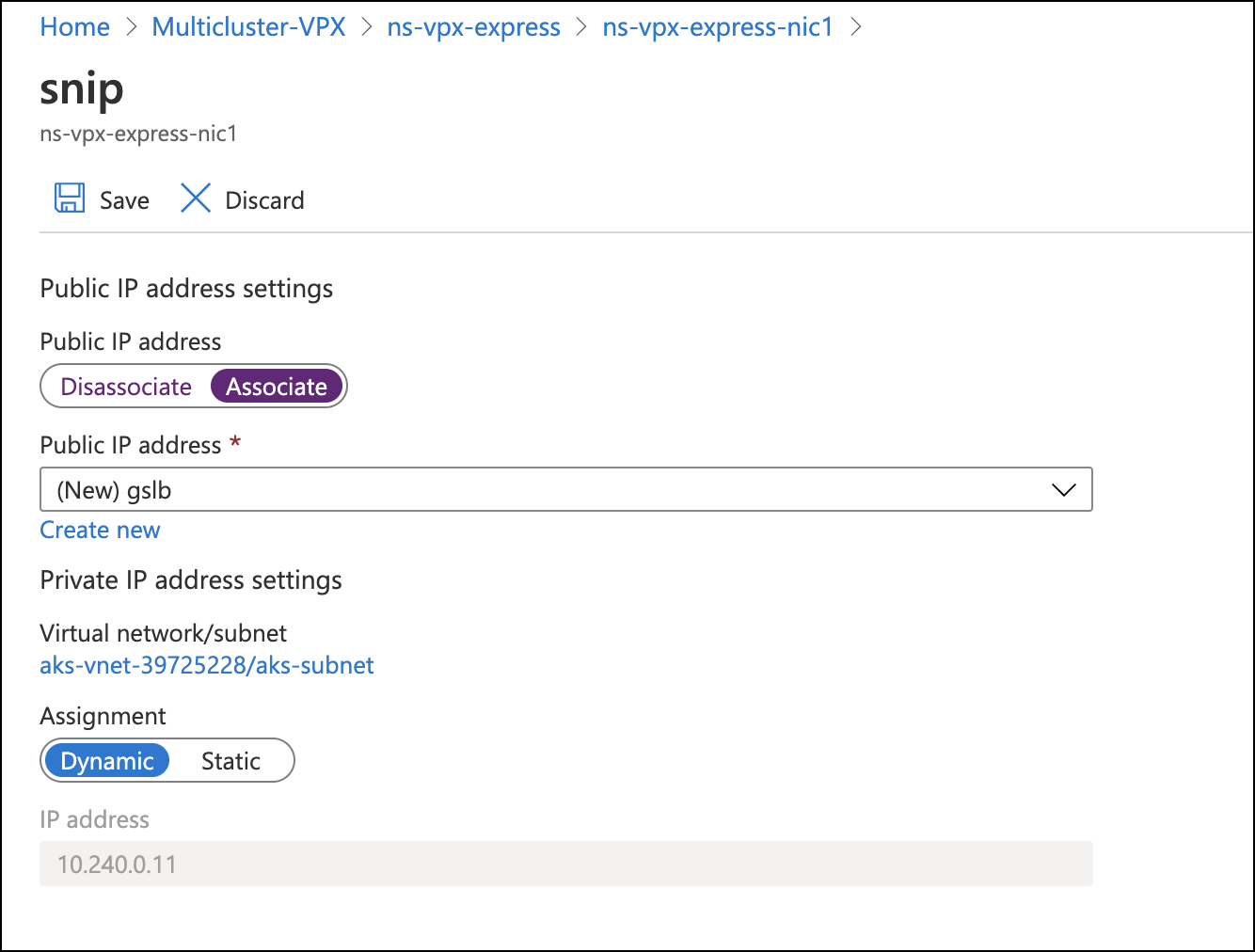
You must have a SNIP with public IP for GSLB sync and ADNS service. If SNIP already exists, associate a public IP address with it.
-
To associate, choose Home > Resource group > VPX instance > VPX NIC instance. Associate a public IP address as shown in the following image. Click Save to save the changes.

-
Log in to the Azure NetScaler VPX instance and add the secondary IP as SNIP with the management access enabled using the following command:
add ip 10.240.0.11 255.255.0.0 -type SNIP -mgmtAccess ENABLEDIf the resource exists, you can use the following command to set the management access enabled on the existing resource.
set ip 10.240.0.11 -mgmtAccess ENABLED -
Enable CS, LB, SSL, and GSLB features in the NetScaler VPX using the following command:
enable feature *feature*To access the NetScaler VPX instance through SSH, you must enable the inbound port rule for the SSH port in the Azure network security group that is attached to the NetScaler VPX primary interface.
-
Enable the inbound rule for the following ports in the network security group on the Azure portal.
- TCP: 3008–3011 for GSLB metric exchange
- TCP: 22 for SSH
- TCP and UDP: 53 for DNS
-
Add a nameserver to NetScaler VPX using the following command:
add nameserver *nameserver IP*
Configure ADNS service in NetScaler VPX deployed in AWS and Azure
The ADNS service in NetScaler VPX acts as an authoritative DNS for your domain. For more information on the ADNS service, see Authoritative DNS service.
-
Log in to AWS NetScaler VPX and configure the ADNS service on the secondary IP address and port 53 using the following command:
add service Service-ADNS-1 192.168.211.73 ADNS 53Verify the configuration using the following command:
show service Service-ADNS-1 -
Log in to Azure NetScaler VPX and configure the ADNS service on the secondary IP address and port 53 using the following command:
add service Service-ADNS-1 10.240.0.8 ADNS 53Verify the configuration using the following command:
show service Service-ADNS-1 -
After creating two ADNS service for the domain, update the NS record of the domain to point to the ADNS services in the domain registrar.
For example, create an ‘A’ record
ns1.domain.compointing to the ADNS service public IP address. NS record for the domain must point to ns1.domain.com.
Configure GSLB service in NetScaler VPX deployed in AWS and Azure
You must create GSLB sites on NetScaler VPX deployed on AWS and Azure.
-
Log in to AWS NetScaler VPX and configure GSLB sites on the secondary IP address using the following command. Also, specify the public IP address using the –publicIP argument. For example:
add gslb site aws_site 192.168.197.18 -publicIP 3.139.156.175 add gslb site azure_site 10.240.0.11 -publicIP 23.100.28.121 -
Log in to Azure NetScaler VPX and configure GSLB sites. For example:
add gslb site aws_site 192.168.197.18 -publicIP 3.139.156.175 add gslb site azure_site 10.240.0.11 -publicIP 23.100.28.121 -
Verify that the GSLB sync is successful by initiating a sync from any of the sites using the following command:
sync gslb config –debug
Note:
If the initial sync fails, review the security groups on both AWS and Azure to allow the required ports.
Apply GTP and GSE CRDs on AWS and Azure Kubernetes clusters
The global traffic policy (GTP) and global service entry (GSE) CRDs help to configure NetScaler for performing GSLB in Kubernetes applications. These CRDs are designed for configuring NetScaler GSLB controller for applications deployed in distributed Kubernetes clusters.
GTP CRD
The GTP CRD accepts the parameters for configuring GSLB on the NetScaler including deployment type (canary, failover, and local-first), GSLB domain, health monitor for the ingress, and service type.
For GTP CRD definition, see the GTP CRD. Apply the GTP CRD definition on AWS and Azure Kubernetes clusters using the following command:
kubectl apply -f https://raw.githubusercontent.com/citrix/citrix-k8s-ingress-controller/master/gslb/Manifest/gtp-crd.yaml
GSE CRD
The GSE CRD specifies the endpoint information (information about any Kubernetes object that routes traffic into the cluster) in each cluster. The global service entry automatically picks the external IP address of the application, which routes traffic into the cluster. If the external IP address of the routes change, the global service entry picks a newly assigned IP address and configure the GSLB endpoints of NetScalers accordingly.
For the GSE CRD definition, see the GSE CRD. Apply the GSE CRD definition on AWS and Azure Kubernetes clusters using the following command:
kubectl apply -f https://raw.githubusercontent.com/citrix/citrix-k8s-ingress-controller/master/gslb/Manifest/gse-crd.yaml
Deploy GSLB controller
GSLB controller helps you to ensure the high availability of the applications across clusters in a multi-cloud environment.
You can install the GSLB controller on the AWS and Azure clusters. GSLB controller listens to GTP and GSE CRDs and configures the NetScaler for GSLB that provides high availability across multiple regions in a multi-cloud environment.
To deploy the GSLB controller, perform the following steps:
-
Create an RBAC for the GSLB controller on the AWS and Azure Kubernetes clusters.
kubectl apply -f https://raw.githubusercontent.com/citrix/citrix-k8s-ingress-controller/master/gslb/Manifest/gslb-rbac.yaml -
Create the secrets on the AWS and Azure clusters using the following command:
Note:
Secrets enable the GSLB controller to connect and push the configuration to the GSLB devices.
kubectl create secret generic secret-1 --from-literal=username=<username> --from-literal=password=<password>Note:
You can add a user to NetScaler using the
add system usercommand. -
Download the GSLB controller YAML file from gslb-controller.yaml.
-
Apply the
gslb-controller.yamlin an AWS cluster using the following command:kubectl apply -f gslb-controller.yamlFor the AWS environment, edit the
gslb-controller.yamlto define the LOCAL_REGION, LOCAL_CLUSTER, and SITENAMES environment variables.The following example defines the environment variable
LOCAL_REGIONas us-east-2 andLOCAL_CLUSTERas eks-cluster and theSITENAMESenvironment variable as aws_site,azure_site.name: "LOCAL_REGION" value: "us-east-2" name: "LOCAL_CLUSTER" value: "eks-cluster" name: "SITENAMES" value: "aws_site,azure_site" name: "aws_site_ip" value: "NSIP of aws VPX(internal IP)" name: "aws_site_region" value: "us-east-2" name: "azure_site_ip" value: "NSIP of azure_VPX(public IP)" name: "azure_site_region" value: "central-india" name: "azure_site_username" valueFrom: secretKeyRef: name: secret-1 key: username name: "azure_site_password" valueFrom: secretKeyRef: name: secret-1 key: password name: "aws_site_username" valueFrom: secretKeyRef: name: secret-1 key: username name: "aws_site_password" valueFrom: secretKeyRef: name: secret-1 key: passwordApply the gslb-controller.yaml in the Azure cluster using the following command:
kubectl apply -f gslb-controller.yaml -
For the Azure site, edit the
gslb-controller.yamlto defineLOCAL_REGION,LOCAL_CLUSTER, andSITENAMESenvironment variables.The following example defines the environment variable
LOCAL_REGIONas central-india,LOCAL_CLUSTERas azure-cluster, andSITENAMESas aws_site, azure_site.name: "LOCAL_REGION" value: "central-india" name: "LOCAL_CLUSTER" value: "aks-cluster" name: "SITENAMES" value: "aws_site,azure_site" name: "aws_site_ip" value: "NSIP of AWS VPX(public IP)" name: "aws_site_region" value: "us-east-2" name: "azure_site_ip" value: "NSIP of azure VPX(internal IP)" name: "azure_site_region" value: "central-india" name: "azure_site_username" valueFrom: secretKeyRef: name: secret-1 key: username name: "azure_site_password" valueFrom: secretKeyRef: name: secret-1 key: password name: "aws_site_username" valueFrom: secretKeyRef: name: secret-1 key: username name: "aws_site_password" valueFrom: secretKeyRef: name: secret-1 key: passwordNote: The order of the GSLB site information should be the same in all clusters. The first site in the order is considered as the master site for pushing the configuration. Whenever the master site goes down, the next site in the list becomes the new master. Hence, the order of the sites should be the same in all Kubernetes clusters.
Deploy a sample application
In this example application deployment scenario, an https image of apache is used. However, you can choose the sample application of your choice.
The application is exposed as type LoadBalancer in both AWS and Azure clusters. You must run the commands in both AWS and Azure Kubernetes clusters.
-
Create a deployment of a sample apache application using the following command:
kubectl create deploy apache --image=httpd:latest port=80 -
Expose the apache application as service of type LoadBalancer using the following command:
kubectl expose deploy apache --type=LoadBalancer --port=80 -
Verify that an external IP address is allocated for the service of type LoadBalancer using the following command:
kubectl get svc apache
NAME     TYPE           CLUSTER-IP    EXTERNAL-IP     PORT(S)        AGE
apache   LoadBalancer   10.0.16.231   20.62.235.193   80:32666/TCP   3m2s
After deploying the application on AWS and Azure clusters, you must configure the GTE custom resource to configure high availability in the multi-cloud clusters.
Create a GTP YAML resource gtp_isntance.yaml as shown in the following example.
apiVersion: "citrix.com/v1beta1"
 kind: globaltrafficpolicy
 metadata:
   name: gtp-sample-app
   namespace: default
 spec:
   serviceType: 'HTTP'
   hosts:
   - host: <domain name>
     policy:
       trafficPolicy: 'FAILOVER'
       secLbMethod: 'ROUNDROBIN'
       targets:
       - destination: 'apache.default.us-east-2.eks-cluster'
         weight: 1
       - destination: 'apache.default.central-india.aks-cluster'
         primary: false
         weight: 1
       monitor:
       - monType: http
         uri: ''
         respCode: 200
   status:
     {}
<!--NeedCopy-->
In this example, traffic policy is configured as FAILOVER. However, the multi-cluster controller supports multiple traffic policies. For more information, see the documentation for the traffic policies.
Apply the GTP resource in both the clusters using the following command:
kubectl apply -f gtp_instance.yaml
You can verify that the GSE resource is automatically created in both of the clusters with the required endpoint information derived from the service status. Verify using the following command:
kubectl get gse
kubectl get gse *name* -o yaml
Also, log in to NetScaler VPX and verify that the GSLB configuration is successfully created using the following command:
show gslb runningconfig
As the GTP CRD is configured for the traffic policy as FAILOVER, NetScaler VPX instances serve the traffic from the primary cluster (EKS cluster in this example).
curl -v http://*domain_name*
However, if an endpoint is not available in the EKS cluster, applications are automatically served from the Azure cluster. You can ensure it by setting the replica count to 0 in the primary cluster.
NetScaler VPX as ingress and GSLB device for Amazon EKS and Microsoft AKS clusters
You can deploy the multi-cloud and multi-cluster ingress and load balancing solution with Amazon EKS and Microsoft AKS with NetScaler VPX as GSLB and the same NetScaler VPX as ingress device too.
To deploy the multi-cloud multi-cluster ingress and load balancing with NetScaler VPX as the ingress device, you must complete the following tasks described in the previous sections:
- Deploy NetScaler VPX in AWS
- Deploy NetScaler VPX in Azure
- Configure ADNS service on NetScaler VPX deployed in AWS and AKS
- Configure GSLB service on NetScaler VPX deployed in AWS and AKS
- Apply GTP and GSE CRDs on AWS and Azure Kubernetes clusters
- Deploy the GSLB controller
After completing the preceding tasks, perform the following tasks:
- Configure NetScaler VPX as Ingress Device for AWS
- Configure NetScaler VPX as Ingress Device for Azure
Configure NetScaler VPX as Ingress device for AWS
Perform the following steps:
-
Create NetScaler VPX login credentials using Kubernetes secret
kubectl create secret generic nslogin --from-literal=username='nsroot' --from-literal=password='<instance-id-of-vpx>'The NetScaler VPX password is usually the instance-id of the VPX if you have not changed it.
-
Configure SNIP in the NetScaler VPX by connecting to the NetScaler VPX using SSH. SNIP is the secondary IP address of Citrix a VPX to which the elastic IP address is not assigned.
add ns ip 192.168.84.93 255.255.224.0This step is required for NetScaler to interact with the pods inside the Kubernetes cluster.
-
Update the NetScaler VPX management IP address and VIP in the NetScaler Ingress Controller manifest.
wget https://raw.githubusercontent.com/citrix/citrix-k8s-ingress-controller/master/deployment/aws/quick-deploy-cic/manifest/cic.yamlNote:
If you do not have
wgetinstalled, you can usefetchorcurl. -
Update the primary IP address of NetScaler VPX in the
cic.yamlin the following field.# Set NetScaler NSIP/SNIP, SNIP in case of HA (mgmt has to be enabled) - name: "NS_IP" value: "X.X.X.X" -
Update the NetScaler VPX VIP in the
cic.yamlin the following field. This is the private IP address to which you have assigned an elastic IP address# Set NetScaler® VIP for the data traffic - name: "NS_VIP" value: "X.X.X.X" -
Once you have edited the YAML file with the required values deploy NetScaler Ingress Controller.
kubectl create -f cic.yaml
Configure NetScaler VPX as Ingress device for Azure
Perform the following steps:
-
Create NetScaler VPX login credentials using Kubernetes secrets.
kubectl create secret generic nslogin --from-literal=username='<azure-vpx-instance-username>' --from-literal=password='<azure-vpx-instance-password>'Note:
The NetScaler VPX user name and password should be the same as the credentials set while creating NetScaler VPX on Azure.
-
Using SSH, configure a SNIP in the NetScaler VPX, which is the secondary IP address of the NetScaler VPX. This step is required for the NetScaler to interact with pods inside the Kubernetes cluster.
add ns ip <snip-vpx-instance-private-ip> <vpx-instance-primary-ip-subnet>-
snip-vpx-instance-private-ipis the dynamic private IP address assigned while adding a SNIP during the NetScaler VPX instance creation. -
vpx-instance-primary-ip-subnetis the subnet of the primary private IP address of the NetScaler VPX instance.
To verify the subnet of the private IP address, SSH into the NetScaler VPX instance and use the following command.
show ip <primary-private-ip-addess> -
-
Update the NetScaler VPX image URL, management IP address, and VIP in the NetScaler Ingress Controller YAML file.
-
Download the NetScaler Ingress Controller YAML file.
wget https://raw.githubusercontent.com/citrix/citrix-k8s-ingress-controller/master/deployment/azure/manifest/azurecic/cic.yamlNote:
If you do not have
wgetinstalled, you can use thefetchorcurlcommand. -
Update the NetScaler Ingress Controller image with the Azure image URL in the
cic.yamlfile.- name: cic-k8s-ingress-controller # CIC Image from Azure image: "<azure-cic-image-url>" -
Update the primary IP address of the NetScaler VPX in the
cic.yamlwith the primary private IP address of the Azure VPX instance.# Set NetScaler NSIP/SNIP, SNIP in case of HA (mgmt has to be enabled) - name: "NS_IP" value: "X.X.X.X" -
Update the NetScaler VPX VIP in the
cic.yamlwith the private IP address of the VIP assigned during VPX Azure instance creation.# Set NetScaler VIP for the data traffic - name: "NS_VIP" value: "X.X.X.X"
-
-
Once you have configured NetScaler Ingress Controller with the required values, deploy the NetScaler Ingress Controller using the following command.
kubectl create -f cic.yaml
In this article
- Deployment topology
- Prerequisites
- Deploying NetScaler VPX in AWS
- Deploying NetScaler VPX in Azure
- Configure ADNS service in NetScaler VPX deployed in AWS and Azure
- Configure GSLB service in NetScaler VPX deployed in AWS and Azure
- Apply GTP and GSE CRDs on AWS and Azure Kubernetes clusters
- Deploy GSLB controller
- NetScaler VPX as ingress and GSLB device for Amazon EKS and Microsoft AKS clusters