Configuration
After you have installed the SD-WAN software and licenses, you can configure SD-WAN appliance settings to start managing your network and deployment.
Initial Setup
These procedures must be completed for each appliance you want to add to your SD-WAN. Consequently, this process will require some coordination with your Site Administrators across your network, to ensure the appliances are prepared and ready to deploy at the proper time. However, once the Master Control Node (MCN) is configured and deployed, you can add client appliances (client nodes) to your SD-WAN at any time.
For each appliance you want to add to your Virtual WAN, you will need to do the following.
-
Set up the SD-WAN Appliance hardware and any SD-WAN VPX Virtual Appliances (SD-WAN VPX-VW) you will be deploying.
-
Set the Management IP Address for the appliance and verify the connection.
-
Set the date and time on the appliance.
-
Set the console session Timeout threshold to a high or the maximum value.
Warning
If your console session times out or you log out of the Management Web Interface before saving your configuration, any unsaved configuration changes will be lost. You must then log back into the system, and repeat the configuration procedure from the beginning. For that reason, it is strongly recommended that you set the console session Timeout interval to a high value when creating or modifying a configuration package, or performing other complex tasks.
-
Upload and install the software license file on the appliance.
For instructions on installing a SD-WAN Virtual Appliance (SD-WAN VPX), see the following sections:
Overview of Web Interface (UI) Layout
This section provides basic navigation instructions, and a navigation roadmap of the SD-WAN web management interface page hierarchy.
Basic navigation
The below figure outlines the basic navigation elements of the Web Management Interface, and the terminology used to identify them.
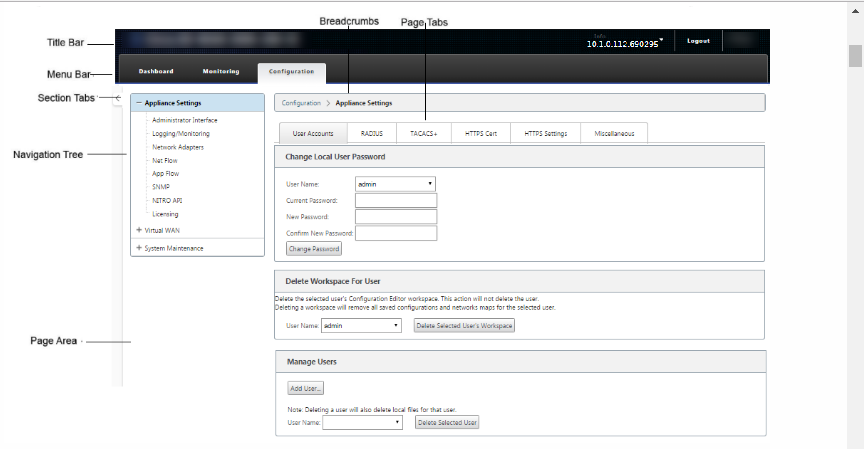
The basic navigation elements are as follows:
-
Title bar – This displays the appliance model number, Host IP Address for the appliance, the version of the software package currently running on the appliance, and the user name for the current login session. The title bar also contains the Logout button for terminating the session.
-
Main menu bar – This is the bar displayed below the title bar on every Management Web Interface screen. This contains the section tabs for displaying the navigation tree and pages for a selected section.
-
Section tabs – The section tabs are located in the main menu bar at the top of the page. These are the top-level categories for the Web Management Interface pages and forms. Each section has its own navigation tree for navigating the page hierarchy in that section. Click a section tab to display the navigation tree for that section.
-
Navigation tree – The navigation tree is located in the left pane, below the main menu bar. This displays the navigation tree for a section. Click a section tab to display the navigation tree for that section. The navigation tree offers the following display and navigation options:
-
Click a section tab to display the navigation tree and page hierarchy for that section.
-
Click + (plus sign) next to a branch in the tree to reveal the available pages for that branch topic.
-
Click a page name to display that page in the page area.
-
Click – (minus sign) next to a branch item to close the branch.
-
-
Breadcrumbs – This displays the navigation path to the current page. The breadcrumbs are at the top of the page area, just below the main menu bar. Active navigation links display in blue font. The name of the current page is displayed in black bold font.
-
Page area – This is the page display and work area for the selected page. Select an item in the navigation tree to display the default page for that item.
-
Page tabs – Some pages contain tabs for displaying more child pages for that topic or configuration form. These are located at the top of the page area, just below the breadcrumbs display. Sometimes (as for the Change Management wizard), tabs are located in the left pane of the page area, between the navigation tree and the work area of the page.
-
Page area resizing – For some pages, you can grow or shrink the width of the page area (or sections of it) to reveal more fields in a table or form. Where this is the case, there is a gray, vertical resize bar on the right border of a page area pane, form, or table. Roll your cursor over the resize bar until the cursor changes to a bi-directional arrow. Then click and drag the bar to the right or left to grow or shrink the area width.
If the resize bar is not available for a page, you can click and drag the right edge of your browser to display the full page.
Web management interface dashboard
Click the Dashboard section tab to display basic information for the local appliance.
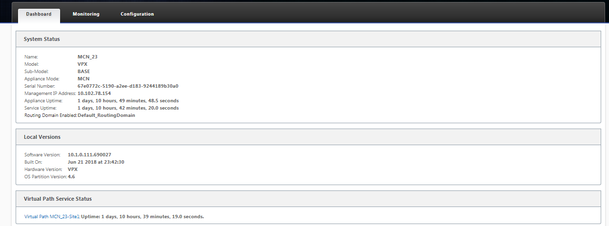
The Dashboard page displays the following basic information for the appliance:
-
System status
-
Virtual Path service status
-
Local appliance software package version information
The following figure shows a sample Master Control Node (MCN) appliance Dashboard display.
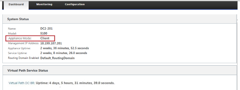
The following figure shows a sample client appliance Dashboard display.
Setting up the Appliance Hardware
To set up Citrix SD-WAN™ appliance hardware (physical appliance), do the following:
-
Set up the chassis.
Citrix SD-WAN Appliances can be installed in a standard rack. For desktop installation, place the chassis on a flat surface. Ensure that there is a minimum of 2 inches of clearance at the sides and back of the appliance, for proper ventilation.
-
Connect the Power.
- Ensure the power switch is set to Off.
- Plug the power cord into the appliance and an AC outlet.
- Press the power button on the front of the appliance.
-
Connect the power.
- Ensure the power switch is set to Off.
- Plug the power cord into the appliance and an AC outlet.
- Press the power button on the front of the appliance.
-
Connect the appliance Management Port to a personal computer.
You need to connect the appliance to a PC in preparation for completing the next procedure, setting the Management IP Address for the appliance.
Note
Before you connect the appliance, ensure the Ethernet port is enabled on the PC. Use an Ethernet cable to connect the SD-WAN Appliance Management Port to the default Ethernet port on a personal computer.
SD-WAN VPX-SE Management Port
The SD-WAN VPX-SE Virtual Appliance is a Virtual Machine, so there is no physical Management Port. However, if you did not configure the Management IP Address for the SD-WAN VPX-SE when you created the VPX Virtual Machine, you need to do so now, as outlined in the section, Configuring the Management IP Address for the SD-WAN VPX-SE.
The SD-WAN VPX-SE Virtual Appliance is a Virtual Machine, so there is no physical Management Port. However, if you did not configure the Management IP Address for the SD-WAN VPX-SE when you created the VPX Virtual Machine, you need to do so now, as outlined in the section, Configuring the Management IP Address for the SD-WAN VPX-SE.
Configure Management IP Address
To enable remote access to an SD-WAN appliance, you must specify a unique Management IP Address for the appliance. To do so, you must first connect the appliance to a PC. You can then open a browser on the PC and connect directly to the Management Web Interface on the appliance, where you can set the Management IP Address for that appliance. The Management IP Address must be unique for each appliance.
Citrix SD-WAN appliances support both IPv4 and IPv6 protocols. You can configure IPv4, IPv6, or both (dual stack). When both IPv4 and IPv6 protocols are configured, the IPv4 protocol takes precedence over the IPv6 protocol.
NOTE
To configure an IPv4 or IPv6 address in feature specific configurations, ensure that the same protocol is enabled and configured as the management interface protocol. For example, if you want to configure an IPv6 address for an SMTP server, ensure that an IPv6 address is configured as the management interface address.
Link-local addresses (IPv6 addresses starting with “fe80”) are not allowed.
To configure an IPv6 address, you must have a router in the network that advertises IPv6 address.
The procedures are different for setting the Management IP Address for a hardware SD-WAN Appliance and a VPX Virtual Appliance (Citrix SD-WAN VPX-SE). For instructions for configuring the address for each type of appliance, see the following:
- SD-WAN VPX Virtual Appliance – See the sections, [Configuring the Management IP Address for the SD-WAN VPX-SE and Differences Between an SD-WAN VPX-SE and SD-WAN WANOP VPX Installation.
To configure the Management IP Address for a hardware SD-WAN Appliance, do the following:
Note
You must repeat the following process for each hardware appliance you want to add to your network.
-
If you are configuring a hardware SD-WAN appliance, physically connect the appliance to a PC.
- If you have not already done so, connect one end of an Ethernet cable to the Management Port on the appliance, and the other end to the default Ethernet port on the PC.
Note
Ensure that the Ethernet port is enabled on the PC you are using to connect to the appliance.
-
Record the current Ethernet port settings for the PC you are using to set the appliance Management IP Address.
You must change the Ethernet port settings on the PC before you can set the appliance Management IP Address. Be sure to record the original settings so you can restore them after configuring the Management IP Address.
-
Change the IP Address for the PC.
On the PC, open your network interface settings and change the IP Address for your PC to the following:
- 192.168.100.50
-
Change the Subnet Mask setting on your PC to the following:
- 255.255.0.0
-
On the PC, open a browser and enter the default IP Address for the appliance. Enter the following IP Address in the address line of the browser:
- 192.168.100.1
Note
It is recommended that you use Google Chrome browser when connecting to an SD-WAN appliance.
Ignore any browser certificate warnings for the Management Web Interface.
This opens the SD-WAN management web interface login screen on the connected appliance.
-
Enter the administrator user name and password, and click Login.
-
Default administrator user name: admin
-
Default administrator password: password
Note
It is recommended that you change the default password. Be sure to record the password in a secure location, as password recovery might require a configuration reset.
After you have logged into the management web interface, the Dashboard page displays, as shown below.

The first time you log into the management web interface on an appliance, the Dashboard displays an Alert icon (goldenrod delta) and alert message indicating that the SD-WAN Service is disabled, and the license has not been installed. For now, you can ignore this alert. The alert will be resolved after you have installed the license, and completed the configuration and deployment process for the appliance.
-
-
In the main menu bar, select the Configuration section tab.
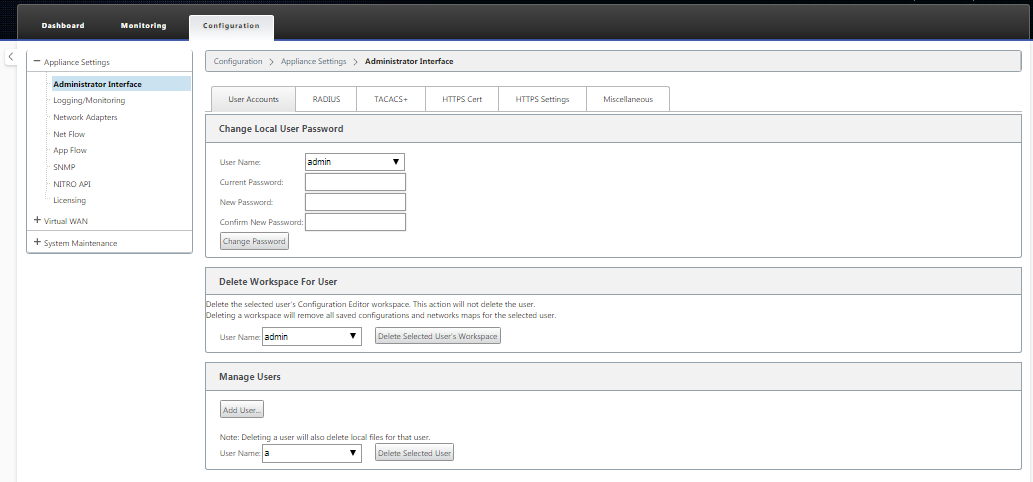
This displays the Configuration navigation tree in the left pane of the screen. The Configuration navigation tree contains the following three primary branches:
- Appliance Settings
- Virtual WAN
- System Maintenance
When you select the Configuration tab, the Appliance Settings branch automatically opens, with the Administrator Interface page preselected by default, as shown in the below figure.
-
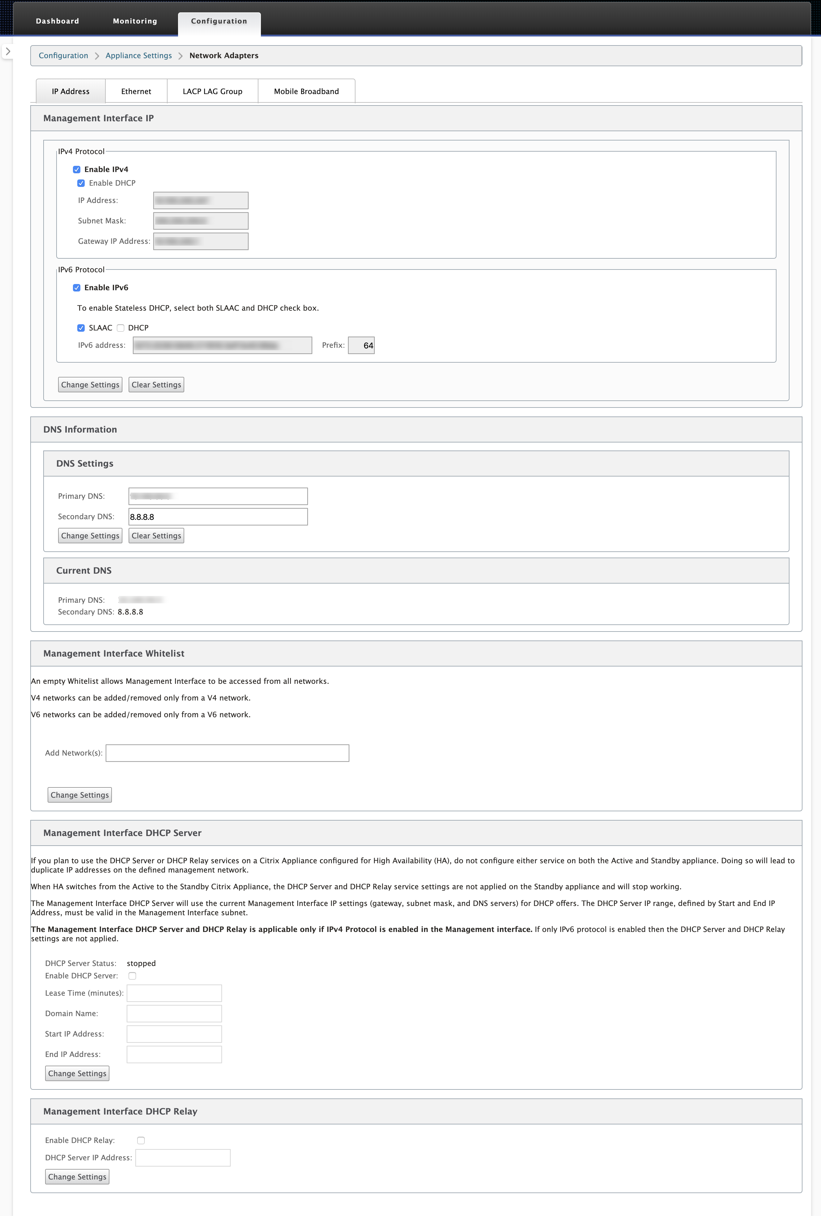
In the Appliance Settings branch of the navigation tree, select Network Adapters. This displays the Network Adapters settings page with the IP Address tab preselected by default, as shown in the below figure.
-
In the IP Address tab, enable one of the following:
-
IPv4 Protocol: To enable IPv4 address, select the Enable IPv4 check box. Dynamic Host Control Protocol (DHCP) assigns an IP address and other network configuration parameters dynamically to each device on the network. Select Enable DHCP for assigning IP address dynamically. To configure the IP address manually, provide the following details:
- IP Address
- Subnet Mask
- Gateway IP Address
-
IPv6 Protocol: To enable IPv6 address, select Enable IPv6 check box. You can configure IPv6 address manually or enable DHCP or SLAAC to assign IP address automatically.
To configure manually, provide the following details:
- IP Address
- Prefix
To configure SLAAC, select the SLAAC check box. SLAAC automatically assigns an IPv6 address to each device on the network. SLAAC enables an IPv6 client to generate its own addresses using a combination of locally available information and information advertised by routers through Neighbor Discovery Protocol (NDP).
To configure DHCP, select the DHCP check box. To enable stateless DHCP, select both SLAAC and DHCP check boxes.
- Both IPv4 and IPv6 Protocols: Select both Enable IPv6 and Enable IPv4 check boxes to enable both IPv4 and IPv6 protocols. In such scenarios, the SD-WAN appliance has one IPv4 management IP address and one IPv6 management address.
NOTE
- The management IP address must be unique for each appliance.
- The Management Interface DHCP Server and DHCP Relay sections on the IP Address tab are applicable only if IPv4 Protocol is enabled in the Management interface.
- When the management interface acts as the DHCP client, the host name is used in DHCP client messages as option 12. From Citrix SD-WAN release 11.2.3 onwards and up to release 11.4.1, the host name was set as sdwan. From Citrix SD-WAN release 11.4.1 onwards, the host name is the same as the site name. If the site name is changed or configured for the first time, then until the configuration update is completed and the virtual WAN service is up, the old site name or sdwan is used as the host name in DHCP client messages. After the configuration update is completed and the virtual WAN service is up, the subsequent DHCP client messages use the new site name.
-
IPv4 Protocol: To enable IPv4 address, select the Enable IPv4 check box. Dynamic Host Control Protocol (DHCP) assigns an IP address and other network configuration parameters dynamically to each device on the network. Select Enable DHCP for assigning IP address dynamically. To configure the IP address manually, provide the following details:
-
Click Change Settings. A confirmation dialog box displays, prompting you to verify that you want to change these settings.
-
Click OK.
-
Change the network interface settings on your PC back to the original settings.
Note
Changing the IP address for your PC automatically closes the connection to the appliance, and terminates your login session on the management web interface.
-
Disconnect the appliance from the PC and connect the appliance to your network router or switch. Disconnect the Ethernet cable from the PC, but do not disconnect it from your appliance. Connect the free end of the cable to your network router or switch.
The SD-WAN appliance is now connected to and available on your network.
-
Test the connection. On a PC connected to your network, open a browser and enter the Management IP Address you configured for the appliance in the following format:
For IPv4 address:
https://<IPv4 address>Example:
https://10.10.2.3For IPv6 address:
https://<[IPv6 address]>Example:
https://[fd73:xxxx:yyyy:26::9]If the connection is successful, this displays the Login screen for the SD-WAN management web interface on the appliance you configured.
Tip
After verifying the connection, do not log out of the management web interface. You are using it to complete the remaining tasks outlined in the subsequent sections.
You have now set the management IP address of your SD-WAN appliance, and can connect to the appliance from any location in your network.
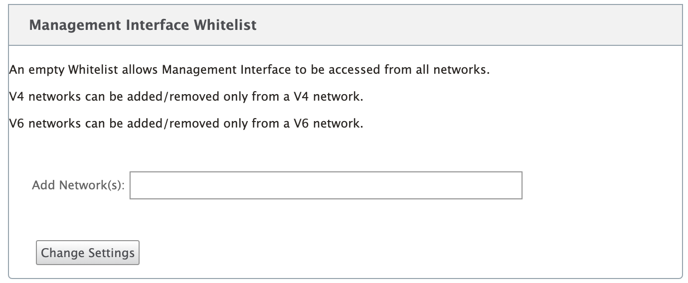
Management interface allow list
Allowed list is an approved list of IP addresses or IP domains that have permission to access your management interface. An empty list allows Management Interface to be accessed from all networks. You can add IP addresses to ensure that the management IP address is accessible only by the trusted networks.
To add or remove an IPv4 address to the allowed list, you must access the SD-WAN appliance management interface using an IPv4 address only. Similarly, to add or remove an IPv6 address to the allowed list, you must access the SD-WAN appliance management interface using an IPv6 address only.
Set date and time
Before installing the SD-WAN software license on an appliance, you must set the date and time on the appliance.
Note
You must repeat this process for each appliance you want to add to your network.
If the current time is changed either manually or through NTP server, and the newly set time is more than the session time-out timer, then the UI session gets logged out.
To set the date and time, do the following:
- Log into the Management Web Interface on the appliance you are configuring.
-
In the main menu bar, select the Configuration tab.
This displays the Configuration navigation tree in the left pane of the screen.
-
Open the System Maintenance branch in the navigation tree.
-
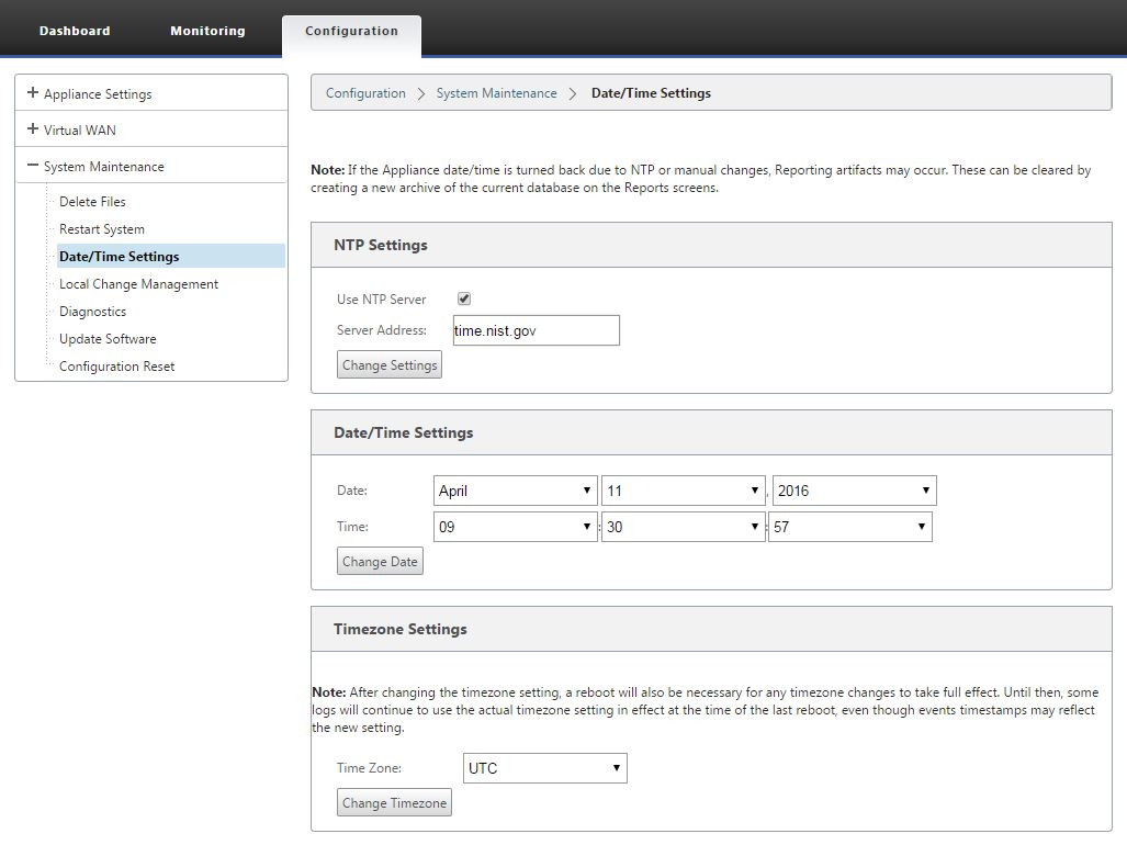
Under the System Maintenance branch, select Date/Time Settings. This displays the Date/Time Settings page, as following.
-
Select the time zone from the Time Zone field drop-down menu at the bottom of the page.
Note
If you have to change the time zone setting, you must do this before setting the date and time, or your settings do not persist as entered.
- Click Change Timezone. This updates the time zone and recalculates the current date and time setting, accordingly. If you set the correct date and time before this step, then your settings are no longer correct. When the time zone update completes, a success Alert icon (green check mark) and status message displays in the top section of the page.
- (Optional) Enable NTP Server service.
- Select Use NTP Server.
- Enter the server address in the Server Address field.
- Click Change Settings. A success Alert icon (green checkmark) and status message displays when the update completes.
- Select the month, day, and year from the Date field drop-down menus.
- Select the hour, minutes, and seconds from the Time field drop-down menus.
- Click Change Date.
Note:
This updates the date and time setting, but does not display a success Alert icon or status message.
The next step is to set the console session Timeout threshold to the maximum value. This step is optional, but recommended. This prevents the session from terminating prematurely while you are working on the configuration, which can result in a loss of work. Instructions for setting the console session Timeout value are provided in the following section. If you do not want to reset the timeout threshold, you can proceed directly to the section, Uploading and Installing the SD-WAN Software License File.
Warning
If your console session times out or you log out of the Management Web Interface before saving your configuration, any unsaved configuration changes are lost. Log back into the system, and repeat the configuration procedure from the beginning.
Session timeout
If your console session times out or you log out of the Management Web Interface before saving your configuration, any unsaved configuration changes are lost. You must then log back into the system, and repeat the configuration procedure from the beginning. For that reason, it is recommended that you set the console session Timeout interval to a high value when creating or modifying a configuration package, or performing other complex tasks. The default is 60 minutes. The maximum is 9,999 minutes. For security reasons, you should then reset it to a lower threshold after completing those tasks.
To reset the console session Timeout interval, do the following:
-
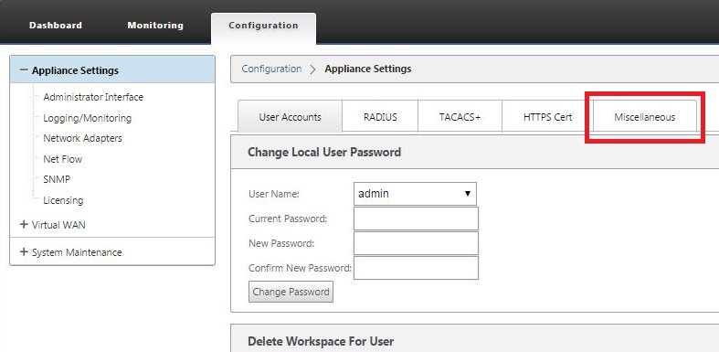
Select the Configuration tab, and then select the Appliance Settings branch in the navigation tree.
This displays the Appliance Settings page, with the User Accounts tab preselected by default.
-
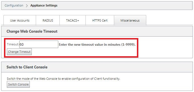
Select the Miscellaneous tab (far right corner).
This displays the Miscellaneous tab page.
-
Enter the console Timeout value.
In the Timeout field of the Change Web Console Timeout section, enter a higher value (in minutes) up to the maximum value of 9999. The default is 60, which is much too brief for an initial configuration session.
Note
For security reasons, be sure to reset this value to a lower interval after completing the configuration and deployment.
-
Click Change Timeout.
This resets the session Timeout interval, and displays a success message when the operation completes.
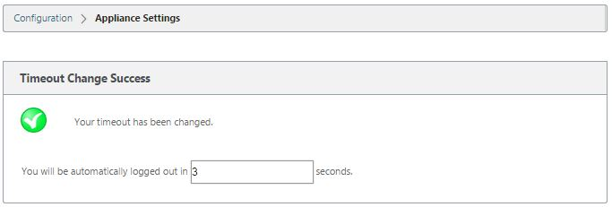
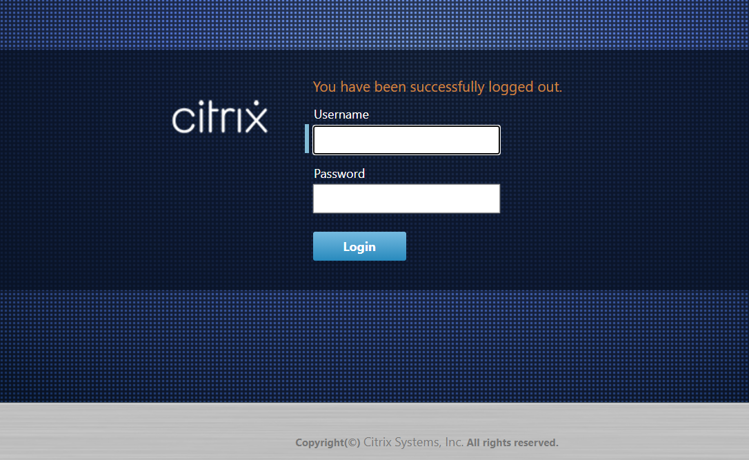
After a brief interval (a few seconds), the session is terminated and you are automatically logged out of the Management Web Interface. The Login page appears.
-
Enter the Administrator user name (admin) and password (password), and click Login.
The next step is to upload and install the SD-WAN software license file on the appliance.
Configure Alarms
You can now configure your SD-WAN appliance to identify alarm conditions based on your network and priorities, generate alerts, and receive notifications via email, syslog, or SNMP trap.
An alarm is a configured alert consisting of an event type, a trigger state, a clear state, and a severity.
To configure alarm settings:
-
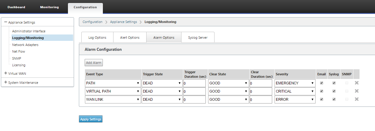
In the SD-WAN web management interface, navigate to Configuration > Appliance Settings > Logging/Monitoring and click Alarm Options.
-
Click Add Alarm to add a new alarm.
-
Select or enter values for the following fields:
- Event Type: The SD-WAN appliance can trigger alarms for particular subsystems or objects in the network, these are called event types. The available event types are SERVICE, VIRTUAL_PATH, WANLINK, PATH, DYNAMIC_VIRTUAL_PATH, WAN_LINK_CONGESTION, USAGE_CONGESTION, FAN, POWER_SUPPLY, PROXY_ARP, ETHERNET, DISCOVERED_MTU, GRE_TUNNEL, and IPSEC_TUNNEL.
- Trigger State: The event state that triggers an alarm for an Event Type. The available Trigger State options depend on the chosen event type.
- Trigger Duration: The duration in seconds, this determines how quickly the appliance triggers an alarm. Enter ‘0’ to receive immediate alerts or enter a value between 15-7200 seconds. Alarms are not triggered, if more events occur on the same object within the Trigger Duration period. More alarms are triggered only if an event persists longer than the Trigger Duration period.
- Clear State: The event state that clears an alarm for an Event Type after the alarm is triggered. The available Clear State options depend on the chosen Trigger State.
- Clear Duration: The duration in seconds, this determines how long to wait before clearing an alarm. Enter ‘0’ to immediately clear the alarm or enter a value between 15-7200 seconds. The alarm is not cleared, if another clear state event occurs on the same object within the specified time.
- Severity: A user-defined field that determines how urgent an alarm is. The severity is displayed in the alerts sent when the alarm is triggered or cleared and in the triggered alarm summary.
- Email: Alarm trigger and clear alerts for the Event Type is sent via email.
- Syslog: Alarm trigger and clear alerts for the Event Type is sent via Syslog.
- SNMP: Alarm trigger and clear alerts for the Event Type is sent via SNMP trap.
-
Continue adding alarms as required.
-
Click Apply Settings.
Viewing triggered alarms
To view a summary of all the triggered alarms:
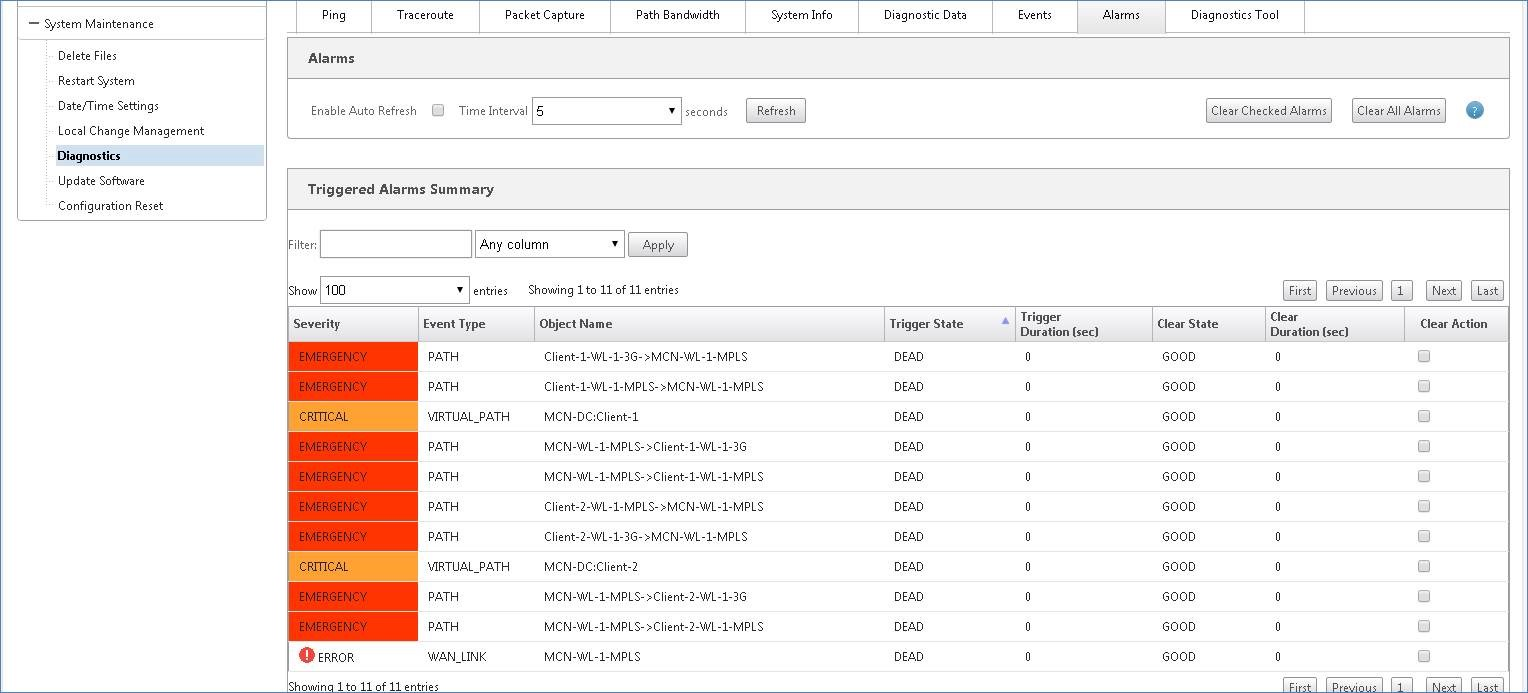
In the SD-WAN web management interface, navigate to Configuration > System Maintenance > Diagnostics > Alarms.
A list of all the triggered alarms is displayed.
Clearing triggered alarms
To manually clear triggered alarms:
- In the SD-WAN web management interface, navigate to Configuration > System Maintenance > Diagnostics > Alarms.
- In the Clear Action column, select the alarms that you want to clear.
- Click Clear Checked Alarms. Alternately, Click Clear All Alarms to clear all the alarms.
Setup Master Control Node
The SD-WAN Master Control Node (MCN) is the head end appliance in the Virtual WAN. Typically, this is a Virtual WAN appliance deployed at the data center. The MCN serves as the distribution point for the initial system configuration and any subsequent configuration changes. In addition, you conduct most upgrade procedures through the Management Web Interface on the MCN. There can be only one active MCN in a Virtual WAN.
By default, appliances have the pre-assigned role of client. To establish an appliance as the MCN, you must first add and configure the MCN site, and then stage and activate the configuration and appropriate software package on the designated MCN appliance.
From Citrix SD-WAN 11.5 release onwards, you can set up an MCN through Citrix SD-WAN Orchestrator service. For more information, see Deployment and Site configuration.
Connecting the client appliances to your network
For an initial deployment, or if you are adding client nodes to an existing SD-WAN, the next step is for the branch site administrators to connect the client appliances to the network at their respective branch sites. This is in preparation for uploading and activating the appropriate SD-WAN appliance packages to the clients. Connect each branch site administrator to initiate and coordinate these procedures.
To connect the site appliances to the SD-WAN, site administrators should do the following:
-
If you have not already done so, set up the client appliances.
For each appliance you want to add to your SD-WAN, do the following:
- Set up the SD-WAN appliance hardware and any SD-WAN VPX virtual appliances (SD-WAN VPX-SE) you are deploying.
- Set the Management IP Address for the appliance and verify the connection.
- Set the date and time on the appliance. Set the console session timeout threshold to a high or the maximum value.
- Upload and install the software license file on the appliance.
-
Connect the appliance to the branch site LAN. Connect one end of an Ethernet cable to a port configured for LAN on the SD-WAN appliance. Then connect other end of the cable to the LAN switch.
-
Connect the appliance to the WAN. Connect one end of an Ethernet cable to a port configured for WAN on the SD-WAN appliance. Then connect the other end of the cable to the WAN router.
The next step is for the branch site administrators to install and activate the appropriate SD-WAN appliance package on their respective clients.
Accessing the shell command
From SD-WAN 11.4.1 release onwards, Admin account users can run the shell command from the SD-WAN CLI console directly, without being prompted for the login credentials of the CBVWSSH static account. This feature enhances the security of your SD-WAN appliances as it removes the hard coded password of the CBVWSSH account and replaces it using a more secure method. To run the shell command, login to the SD-WAN CLI console and type shell.
Note
- This functionality is supported only for Admin account users. It is not supported for Network administrators, Security administrators, or Viewer account users.
- This functionality is meant for troubleshooting purposes only. Any system-specific changes that are made through the
shellcommand are supervised by Citrix.
Upgrade
When you upgrade your SD-WAN appliance to the 11.4.1 version, the password of the default admin account gets synchronized with the CBVWSSH account. This synchronization between the CBVWSSH account and the default admin account happens every time you edit/update the admin account.
Downgrade
When you downgrade your SD-WAN appliance from 11.4.1 to an older version, you get an option to and reset the password of the default admin account. However, the new password does not get synchronized to the CBVWSSH account. Therefore, to be able to access the shell command even after a downgrade, it is mandatory to remember the current password before downgrading your appliance.
Deploy Citrix SD-WAN Standard Edition in OpenStack using CloudInit
You can now deploy Citrix SD-WAN Standard Edition (SE) in an OpenStack environment. For this, Citrix SD-WAN image must support config-drive functionality.
NOTE
Create Citrix® image to support config-drive functionality.
Config-drive functionality supports the following parameter configuration to establish communication with Citrix Orchestrator via the management network:
- Mgmt. ipv4 address
- Mgmt. gateway
- Name-server1
- Name-server2
- Serial number - Used for authentication and it must be reused for the new instance. Serial number passed in clouding must overwrite the autogenerated trial number in the VPX instance.
Note
To reuse the serial number, an init script is incorporated in SD-WAN that run on an OpenStack and change the serial number in /etc/default/family.
Orchestrator must have a unique serial number with SD-WAN appliances to work.
Cloudinit script supports contextualization for SD-WAN deployment in OpenStack with config-drive.
In the process of contextualization, the infrastructure makes the context available to the virtual machine and the virtual machine interprets the context. On contextualization, the virtual machine can start certain services, create users, or set networking and configuration parameters.
For an SD-WAN instance in OpenStack, the inputs needed for Management IP, DNS, and serial number from the users. The Cloudinit script parses these inputs and provision the instance with the given information.
While launching instances in an OpenStack cloud environment, Citrix SD-WAN appliance need to support two technologies that are User Data and CloudInit to support automated configuration of instances at boot time.
Perform the following steps to provisioning SD-WAN SE in an OpenStack environment:
Pre-requisites
Go to Images and click Create Image.
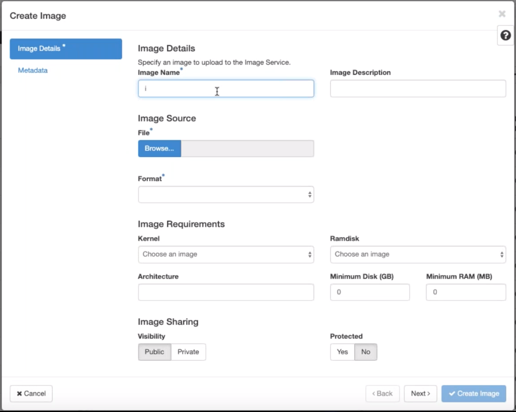
- Image Name - Provide the image name.
- Image Description – Add an image description.
- File - Browse for the kvm.qcow2 image file from your local drive and select it.
- Format – Select the QCOW2 – QEMU Emulator disk format from the drop-down list.
Click Create Image.
Both Network and network port must create initially and predefined. To create network port:
-
Select Networks under Network and go to Port tab.
-
Click Create Port and provide the necessary detail and click Create.
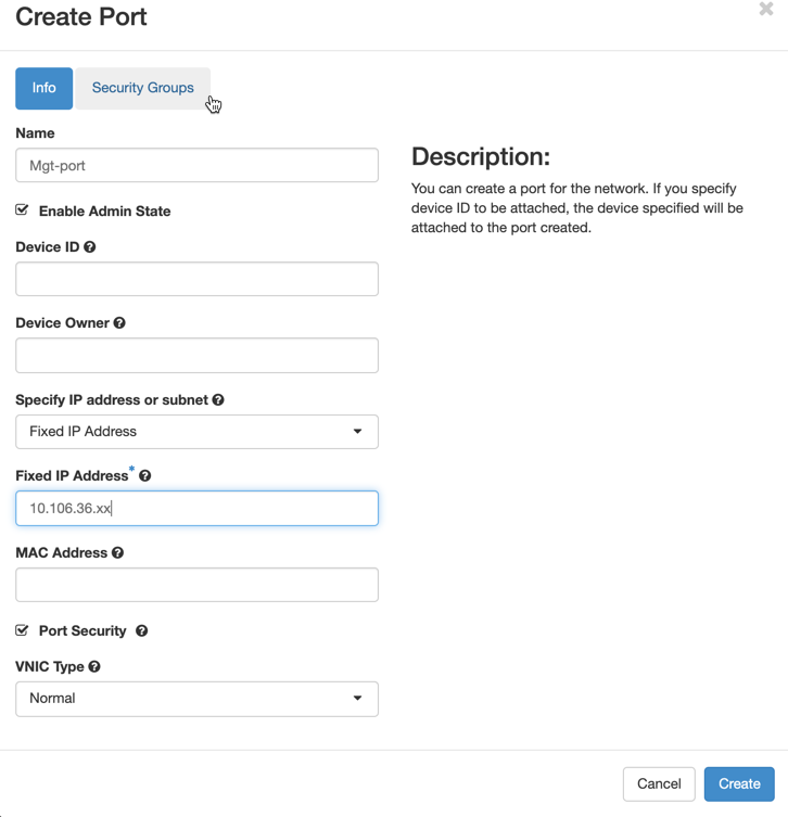
If you select Fixed IP Address, then you must provide the subnet IP address for the new port.
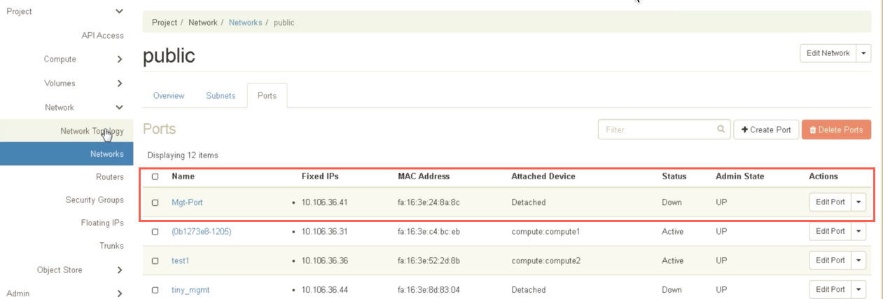
The port is created and as it is not attached to any device, the current status shows Detached.
Create OpenStack instance to enable config-drive and pass the user_data.
-
Log in to OpenStack and configure Instances.
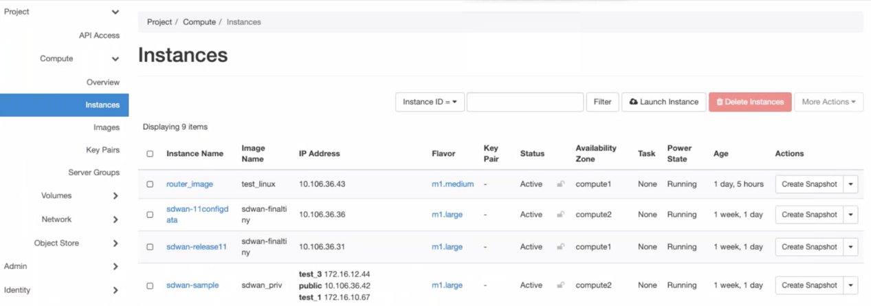
-
Download the kvm.qcow2.gz file and untar it.
-
Go to Instances and click Launch Instance.
NOTE
You can go back to Instances and click Launch Instance or from the Images screen click Launch once the image is created.

-
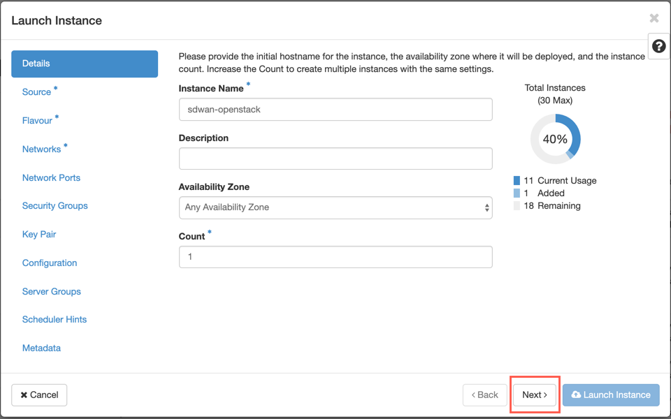
Under Details tab, provide the following information:
- Instance Name – Provide the host name for the instance.
- Description – Add description for the instance.
- Availability Zone – Select the availability zone from the drop-down list where you want to deploy the instance.
- Count – Enter the instance count. You can increase the count to create multiple instances with the same settings. Click Next.
-
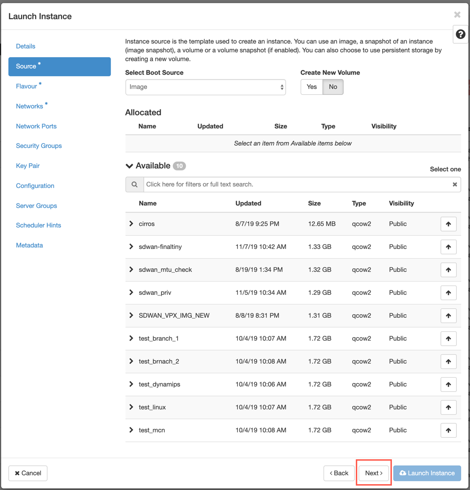
In Source tab, select No under Create New Volume and clickNext. Instance source is the template used to create an instance.
-
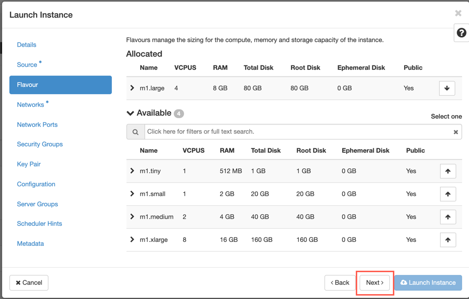
Select Flavour for the instance and click Next. The flavour you select for an instance manages the amount of compute, storage, and memory capacity of the instance.
NOTE
The flavour you select must have enough resources allocated to support the type of instance you are trying to create. Flavours that do not provide enough resources for your instance are identified on the available table with a yellow warning icon.
Administrators are responsible for creating and managing flavours. Click the arrow (at the right side) to allocate.
-
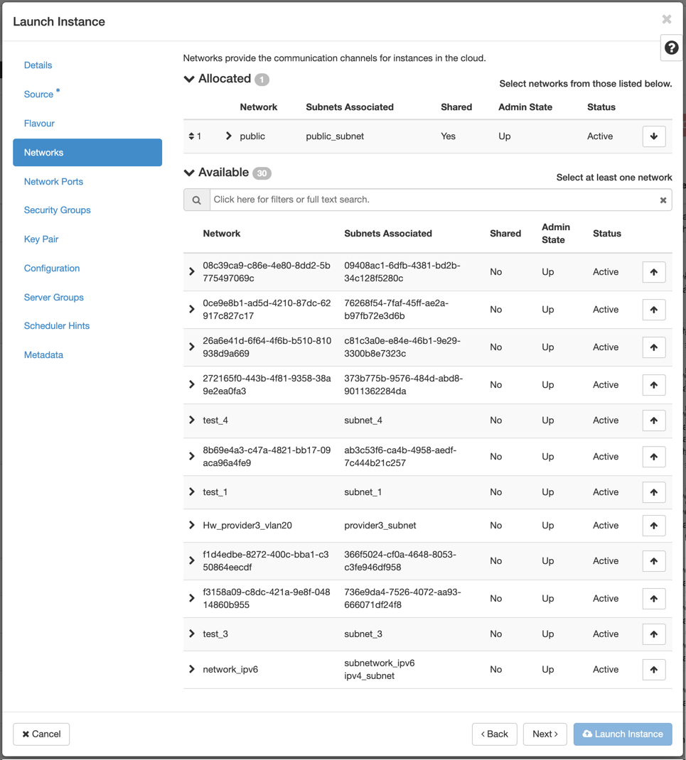
Select the network and click Next. Networks provide the communication channels for instances.
NOTE
An Administrator is created the Provider networks and these networks are map to an existing physical network in the data center. Similarly Project networks are created by Users and these networks are fully isolated and are project-specific.
-
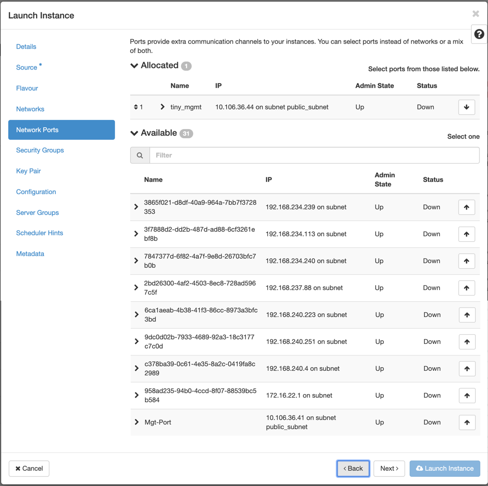
Select a network port for the instance and click Next. Network ports provide additional communication channels to the instances.
NOTE
You can select ports instead of networks or a mix of both.
-
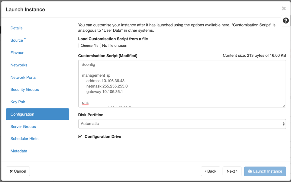
Go to Configuration and click Choose file. Select the user_data file. You can view the Management IP, DNS, and Serial Number information in the user_data file.
-
Enable the Configuration Drive check box. By enabling the configuration drive you can put the user metadata inside the image.
-
Click Launch Instance.