
Deploy a NetScaler cluster on GCP with cloud router using dynamic routing
You can deploy a NetScaler cluster on Google Cloud Platform (GCP) with Google Cloud Router, using dynamic routing to boost the network efficiency. With this setup, you can balance and distribute traffic across multiple paths, making your applications more scalable and reliable.
The deployment process involves configuring both Google Cloud and NetScaler components. The following sections outline the key configuration steps required on each platform:
Google cloud configurations:
NetScaler configurations:
-
Create a NetScaler cluster.
-
Join more nodes to the cluster.
-
Configure BGP dynamic routing and load balancing.
Prerequisites
-
NetScaler VM instances: Deploy the required NetScaler VM instances in GCP, each with at least two network interfaces, one for management or backplane and one for client traffic. Place the VMs in the same region and, for high availability, distribute them across different zones. For detailed deployment steps, see Deploy a NetScaler VPX instance on the Google Cloud Platform.
-
Network setup: Set up a GCP VPC network with appropriate subnets for management, client-side, and back-end server traffic.
-
Firewall rules: Configure firewall rules to allow necessary traffic, such as SSH, HTTPS access to NetScaler, inter-cluster communication, client-to-VIP, and NetScaler-to-backend server connections.
-
NetScaler licenses: Ensure you have valid NetScaler licenses.
-
GCP permissions: Obtain sufficient IAM permissions to create and manage Network Connectivity Center, Cloud Routers, VPNs/Interconnects, and VM network interfaces (including alias IPs).
-
DNS: Set up proper DNS resolution for NetScaler management and VIP addresses.
Deployment steps for a NetScaler cluster with Google Cloud Router using Dynamic Routing
This section includes detailed instructions for configuring both Google Cloud and NetScaler, ensuring seamless integration and optimal performance.
Step 1: Configure NCC hub and spoke in the GCP.
-
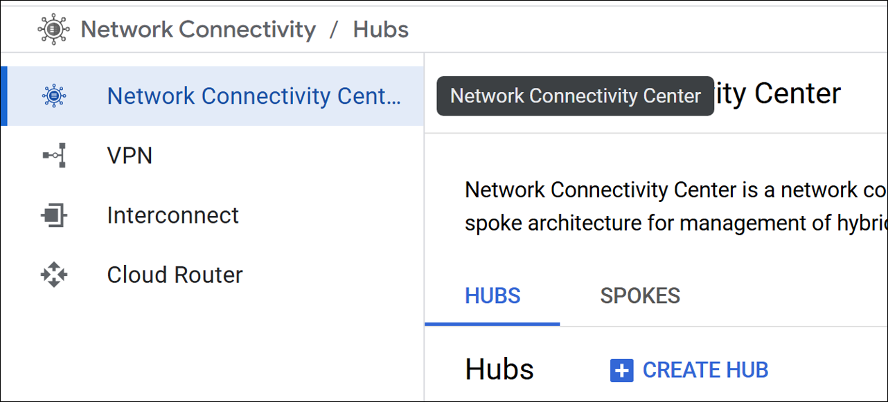
Create a hub. For more information see, Google documentation.In the Google Cloud console, go to the Network Connectivity Center page, and select Create HUB.
-
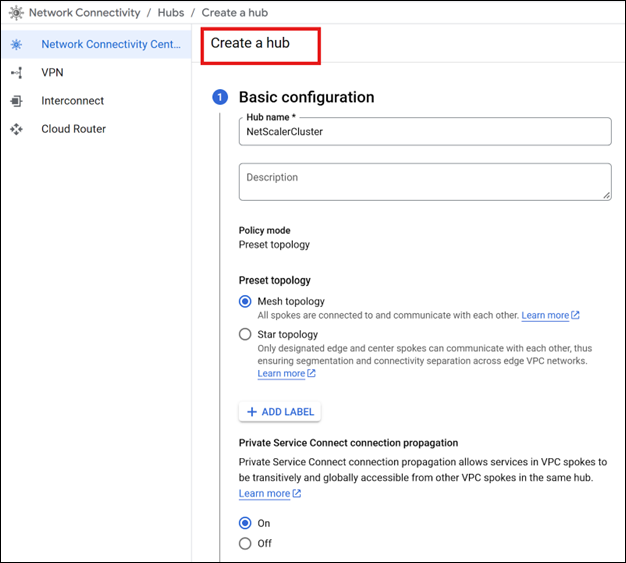
Complete the required basic configurations.
-
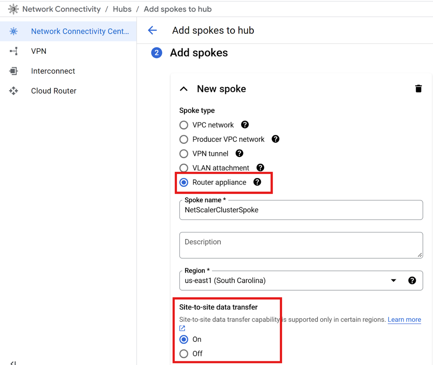
Create a spoke of type Router appliance, and add your NetScaler virtual machine (VM) instances as router appliances in this spoke. For more information see, Google documentation.In the Network Connectivity Center, navigate to the Spokes section and click Add spokes to initiate the spoke creation process.
-
Select the Spoke Type as Router appliance. Make sure that the spoke is created within the same region as your NetScaler VM instances.
-
Ensure that site-to-site data transfer is ON for the spoke to allow route advertisement from the Cloud Router.
-
Step 2: Create cloud router and configure BGP peering with the NetScaler virtual machines on Google Cloud.
-
Create a Cloud Router by following the instructions provided in the Google Cloud documentation.
-
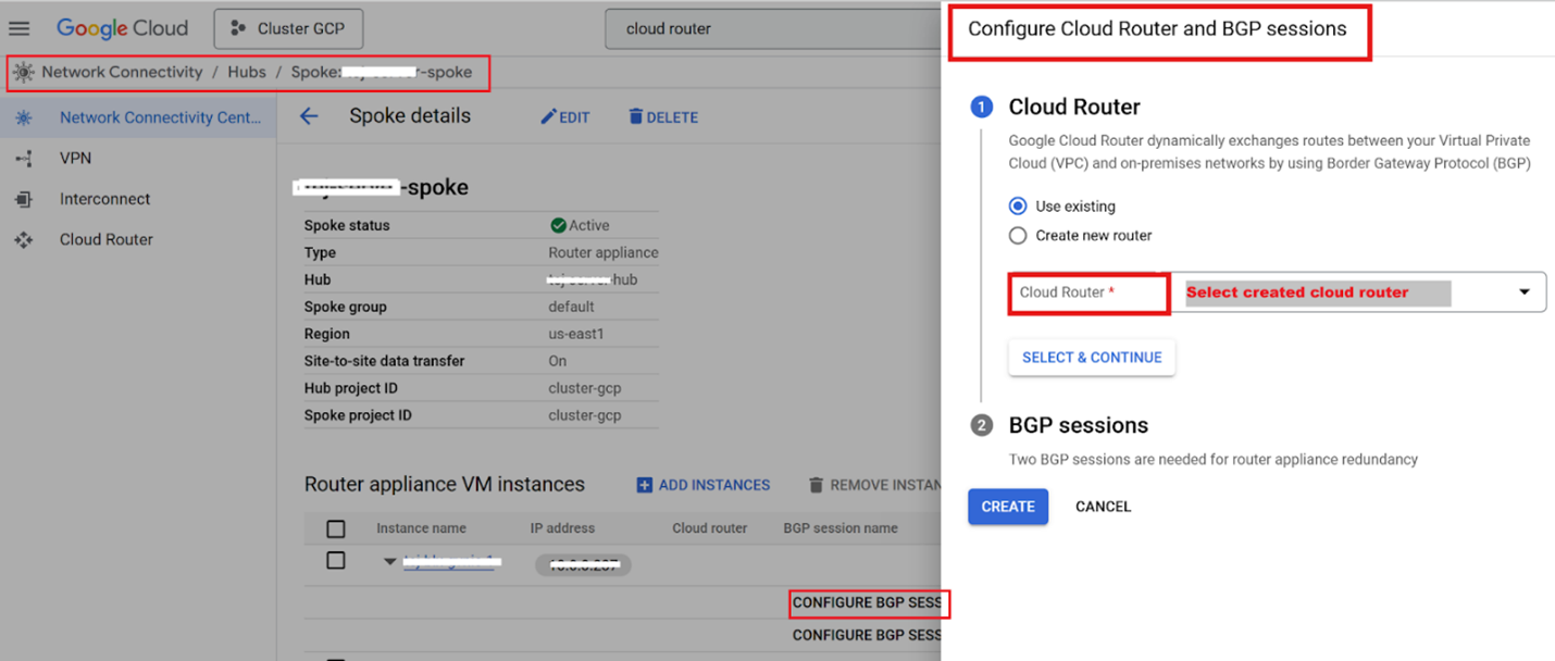
Create the BGP session between the NetScaler and the Cloud Router by navigating to the Network Connectivity Center.
-
Select the appropriate spoke and expand the router instance.
-
Configure the BGP session by selecting the Cloud Router instance and updating the BGP session settings.
-
Add an Autonomous System Number (ASN) of a BGP peer to NetScaler when creating the BGP session. For more information, see Establish BGP sessions.
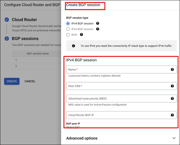
Note:
-
Use the same Peer ASN for all BGP sessions associated with the same cluster nodes.
-
Configuring two BGP sessions, each on a different Cloud Router interface, provides redundancy.
Step 3: Create a NetScaler cluster.
Configure the NetScaler cluster with tunnel mode set to User Datagram Protocol (UDP) and use the management interface as the backplane. For more information, see Setting up a NetScaler cluster.
On the first node, use a management IP/NSIP and set the management interface as the backplane. Reserve a free IP as a static internal IP address on your management Virtual Private Cloud (VPC) network, and attach it as an alias IP address, to the management interface of the first node.
-
Add the cluster instance.At the command prompt, type:
add cluster instance <instanceID>Example:add cluster instance 1 -
Add the first cluster node.At the command prompt, type:
add cluster node <nodeID> <Node NSIP> -state <ACTIVE/PASSIVE/SPARE> -backplane <backplane Interface> -tunnelmode UDPExample:add cluster node 1 10.176.139.121 -state ACTIVE -backplane 1/1/1 -tunnelmode UDP -
Add the cluster IP (CLIP).At the command prompt, type:
add ns ip <CLIP> 255.255.255.255 -type CLIPExample:add ns ip 10.176.139.125 255.255.255.255 -type CLIP -
Enable the cluster instance.At the command prompt, type:
enable cluster instance <instanceID>Example:enable cluster instance 1 -
Save the configuration and reboot.At the command prompt, type:
save config
 reboot -w -f
Note:
The Cluster IP (CLIP) is a floating IP address owned by the Configuration Coordinator (CCO). When the CCO changes, CLIP ownership transfers to the new CCO. On GCP, this transition uses the "updateNetworkInterface" API, which requires correct DNS configuration on the cluster.
Step 4: Join a new node to the cluster.
On the Cluster IP (CLIP), for example with new node NSIP as 10.176.139.123 and management interface 1/1:
-
Add the new cluster node.At the command prompt, type:
add cluster node <nodeID> <Node NSIP> -state <ACTIVE/PASSIVE/SPARE> -backplane <backplane Interface> -tunnelmode UDP
save configExample:add cluster node 2 10.176.139.123 -state PASSIVE -backplane 2/1/1 -tunnelmode UDP
save config -
On the new node’s NSIP, join the cluster, save, and reboot.At the command prompt, type:
join cluster -clip <CLIP> -password <password>
 save config
reboot -w -fExample:join cluster -clip 10.176.139.125 -password ***********
save config
reboot -w -fNote:\>-
After adding a node, make sure to configure all necessary spotted configurations such as Subnet IP (SNIP), VLAN, and interface bindings for the joining node from the CLIP. For more information, see spotted configurations.
-
Configure the linkset on the client-side interface. For more information, see Configuring linksets.The following sample configuration shows how to create and bind a linkset on the client-side interface.
add linkset LS/1
 bind linkset LS/1 -ifnum <client side interface list space separated>
-
-
After the node reboots and successfully joins the cluster, set its state to ACTIVE.
set cluster node <nodeID> -state ACTIVE
Step 5: Configure BGP dynamic routing and load balancing on NetScaler.
For more information on BGP configuration, see Configuring BGP.
-
On the Cluster IP (CLIP), enable the BGP feature.
enable ns feature bgp -
Ensure that each node has a SNIP (Subnet IP) in the client subnet with dynamic routing enabled.
add ns ip <client subnet IP> <netmask> -type SNIP -ownerNode <n> -dynamicRouting ENABLED -
Configure BGP using
vtysh.Example:vtysh
ns#configure terminal
ns(config)#router bgp 61234
ns(config-router)#redistribute kernel
ns(config-router)#neighbor 10.0.2.35 remote-as 65432
ns(config-router)#end
ns#writeNote:61234is the Peer ASN configured on Google Cloud BGP sessions,65432is the Google Router ASN, and10.0.2.35is the Google Router IP. -
Verify BGP status using the following commands:
show ip bgp summary
show ip bgp neighbors -
Enable the load balancing feature and configure a load balancer with a Virtual Private IP (VIP):
enable ns feature lb
add lb vserver <lbvs_name> <serviceType> <VIP> <port> -
Configure Route Health Injection (RHI) for the VIP to advertise it from cluster nodes to the Google Cloud route table:
set ns ip <VIP> -hostRoute ENABLED -vserverRHIlevel <vserverRHILevel> -
Make sure that the VIP is advertised to the GCP VPC route table.