Inline mode
In this mode, the SD-WAN appliance appears to be an Ethernet bridge. Most of the SD-WAN appliance models include a fail-to-wire (Ethernet bypass) feature for inline mode. If power fails, a relay closes and the input and output ports become electrically connected, allowing the Ethernet signal to pass through from one port to another. In the fail-to-wire mode, the SD-WAN appliance looks like a cross-over cable connecting the two ports.
Advantages and Use-cases
The following are the advantages/use cases for the Inline mode deployment:
- Keeping the MPLS router therefore fail-to-wire is a lovely feature. Fail-to-wire capable devices enable seamless failover to underlay infrastructure if the box went down.
- If your devices support fail-to-wire (SD-WAN 210 and above), this allows placing a single SD-WAN inline to hardware bypass the LAN traffic to the customer edge router when the SD-WAN crashes/goes down.
- If the MPLS Links are present that yield a natural extension to the customer’s LAN/Intranet, the fail-to-wire bridge-pair port is the best choice (fail-to-wire capable pairs) such that, when the device crashes or goes down the LAN traffic is hardware bypassed to the customer edge router (still maintained the next hop).
- Networking is simple.
- SD-WAN sees all traffic through the inline mode, so it is the best-case scenario for the proper bandwidth/capacity accounting.
- Few integration requirements as you need only an IP of the L2 segment. LAN segments are well known as you have an arm to the LAN interface. If you connect to a core switch, you can also run dynamic routing to get visibility to all LAN subnets.
- Customer’s expectations are that SD-WAN must blend into the existing infrastructure as a new network node (nothing else changes).
- Proxy ARP - In inline mode, it is a blessing for SD-WAN to proxy ARP requests to LAN next-hop if the gateway went down or the SD-WAN interface towards next-hop went down.
- Generally, in inline mode with bridge-pair (fail-to-block or fail-to-wire) with multiple WAN connections (MPLS/Internet), it is recommended to enable Proxy ARP for the bridge pair interface that connects the LAN hosts to their next-hop gateway.
- For any reason when the next-hop is down or the SD-WAN interface to the next-hop is down rendering the gateway unreachable, SD-WAN acts as a proxy for ARP requests allowing the LAN hosts to still seamlessly send packets and use the remaining WAN connections that keep the virtual path up.
- High availability - If fail-to-wire is not an option, devices can be placed in parallel high availability (common LAN and WAN interfaces for the Active/Standby) devices to achieve redundancy.
- If your appliances don’t support fail-to-wire, like the SD-WAN 110, you have to go with inline parallel high availability that enables to have a standby device kick in if the primary went down.
Recommendations
The following are the recommendations for the Inline mode deployment:
- The inline mode is best for the branches where the existing infrastructure is not to be changed and SD-WAN sits transparently inline to the LAN segment.
- Data centers can also deploy inline fail-to-wire or inline parallel high availability as it is immensely important to ensure that the data center workloads are not blackholed due to device down/crash.
Cautions
The following are the information that you need to be careful about in the Inline mode:
- Plumbing network with two arms to the SD-WAN (LAN and WAN side), needs some downtime as the network must be plumbed in two arms.
- Must ensure if fail-to-wire is used, it is behind a customer edge router/firewall in a TRUSTED zone so that security is not compromised.
- MPLS QoS changes a little in this as the previous QoS policies might have depended on the source IP addresses or DSCP based which will now be masked because of an overlay.
- Care must be taken to repurpose the MPLS router with a well-designed SD-WAN specific reserved bandwidth with a specific DSCP tag, such that SD-WAN’s QoS takes care of prioritizing traffic and sends out high priority applications immediately followed by other classes (but be able to account for the overall bandwidth reserved for SD-WAN on the MPLS router). MPLS queues are an alternative or MPLS with a single DSCP set on the auto path group that can take care of this.
- If the Internet interfaces are TRUSTED as the links terminate on the customer edge router, to use Internet service, you must write an exclusive dynamic NAT rule to enable internet breakout from the appliance.
- If the Internet links are the only WAN connections and still terminate on the customer edge router, it is still fine to bypass the connections if the customer edge router takes precautions to steer the packets via their existing underlay infrastructure.
- Proper care must be taken to account for the flow of bypassing LAN traffic over bridge-pair with an Internet connection and when the appliance is down. Since this is a sensitive enterprise Intranet traffic, in the eve of failure, the customer must know how to handle it.
Before you begin
Before you begin the configuration, ensure that you have a good understanding of the network topology and gathered the details of the site.
The following is an example of an SD-WAN network where a branch is configured in inline mode.
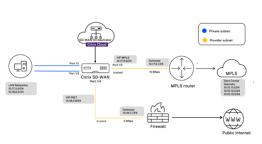
The details of each site are provided in the following table:
| Site details | Inline mode |
|---|---|
| Site Name | Branch 1 |
| Management IP | 172.30.2.20/24 |
| Security Key | If any |
| Model/Edition | 2100 |
| Mode | Inline |
| Topology | 2 x WAN Path |
| VIP Address | 10.17.0.9/24 - MPLS, 10.18.0.9/24 - Internet, Public IP a.b.c.d |
| Gateway MPLS | 10.17.0.1 |
| Gateway Internet | 10.18.0.1 |
| Link Speed | MPLS - 10 Mbps, Internet - 2 Mbps |
| Route | No additional routes were added |
| VLANs | None (default 0) |
Configure inline mode
-
At the customer level configuration, navigate to Configuration > Network Home. Click Add Sites.
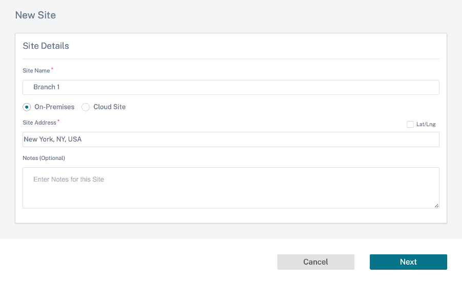
-
Click Next and navigate to Site Details tab. Select the site role as Branch. Click Next and navigate to Device Details tab. Enter the serial number of the appliance.

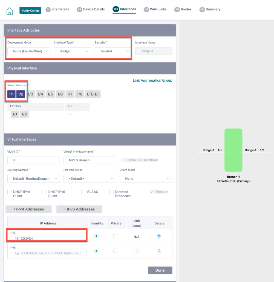
-
Click Next and navigate to Interfaces page. Click + Interface. Select Inline (Fail-To-Wire) as the Deployment mode. Select the interfaces based on your preference and virtual IP addresses. Click Done.
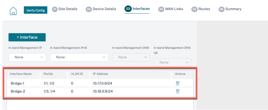
Add two interface pairs in bridge pair mode; one for MPLS and one for Internet.
-
Click Next and navigate to the Interfaces tab. Click + Interface.
-
Select Virtual Inline (One-Arm) from the Deployment Mode drop-down list and One-Arm as the Interface Type. Select the Ethernet interface that connects to the Virtual Inline mode router. As per this topology, add two virtual LANs with the same physical interface; one for MPLS and one for Internet.
To add the first VLAN, in the Virtual Interfaces section, enter the VLAN ID, name for the virtual interface, and IP address. Click Done.
-
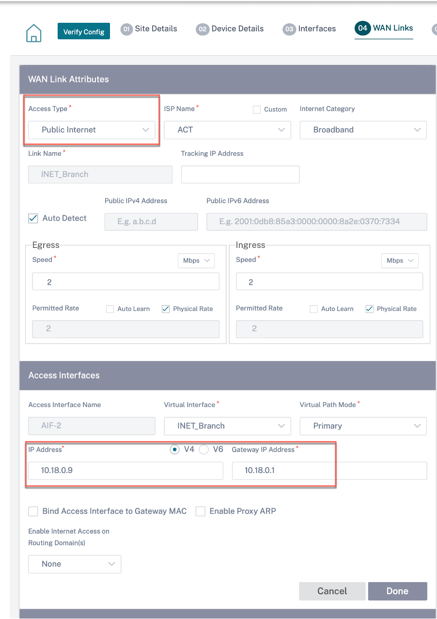
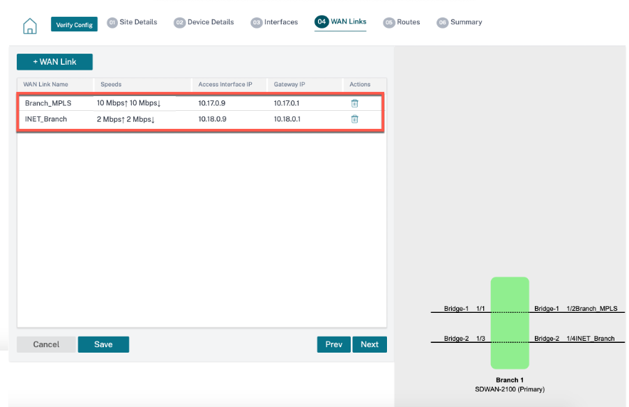
Click Next and navigate to WAN Links tab. Click + WAN Link and select the Create New radio button. Add two WAN links; One for MPLS and one for Internet.
For the internet WAN link, select Public Internet as the Access Type. Select the ISP Name and the name of the WAN link gets populated automatically. Select speed and choose the required virtual interface and the gateway.
For the MPLS WAN link, select MPLS as the Access Type. Select the ISP Name and the name of the WAN link gets populated automatically. Select speed and choose the required virtual interface and the gateway.
Note
If the data center and branches have different ISPs, then you must create an autopath group and include the details of ISPs in it.
-
Click Done and then Save. Click Verify to validate the configurations. If any errors observed, fix them before proceeding further.