Metering and Standby WAN Links
Citrix SD-WAN™ supports enabling metered links, which can be configured such that user traffic is only transmitted on a specific Internet WAN Link when all other available WAN Links are disabled.
Metered links conserve bandwidth on links that are billed based on usage. With the metered links you can configure the links as the Last Resort link, which disallows the usage of the link until all other non-metered links are down or degraded. Set Last Resort is typically enabled when there are three WAN Links to a site (that is, MPLS, Broadband Internet, 4G/LTE) and one of the WAN links is 4G/LTE and may be too costly for a business to allow usage unless it is necessary. Metering is not enabled by default and can be enabled on a WAN link of any access type (Public Internet / Private MPLS / Private Intranet). If metering is enabled, you can optionally configure the following:
- Data cap
- Billing frequency (weekly/monthly)
- Start date of the billing cycle
-
Active heartbeat interval
-
interval at which a heartbeat message is sent by an appliance to its peer on the other end of the virtual path when there has been no traffic (user/control) on the path for at least a heartbeat interval
- configurable values: default 50ms/1s/2s/3s/4s/5s/6s/7s/8s/9s/10s
With a local metered link, the dashboard of an appliance shows a WAN Link Metering table at the bottom with metering information.
Bandwidth usage on a local metered link is tracked against the configured data cap. When the usage exceeds 50%, 75% or 90% of the configured data cap, the appliance generates an event to alert the user and a warning banner is displayed across the top of the dashboard of the appliance. This usage alert event can also be viewed in SD-WAN center. A metered path can be formed with 1 or 2 metered links. If a path is formed between two metered links, the active heartbeat interval used on the metered path is the larger of the two configured active heartbeat intervals on the links.
A metered path is a non-standby path and is always eligible for user traffic. When there is at least one non-metered path that is in GOOD state, a metered path carries reduced amount of control traffic and is avoided when the forwarding plane searches for a path for a duplicate packet.
Standby Mode: The standby mode of a WAN link is disabled by default. To enable standby mode, you must specify in which one of the following two modes the standby link operates
- On-demand: The standby link that becomes active when one of the conditions is met.
-
When the available bandwidth in the virtual path is less than the configured on-demand bandwidth limit AND there is sufficient usage. Sufficient usage is defined as more than 95% (ON_DEMAND_USAGE_THRESHOLD_PCT) of the current available bandwidth, or the difference between current available bandwidth and current usage is less than 250 kbps (ON_DEMAND_THRESHOLD_GAP_KBPS) both parameters can be changed using t2_variables when all the non-standby paths are dead or disabled.
-
Last-resort - a standby link that becomes active only when all non-standby links and on-demand standby links are dead or disabled.
-
When configuring a standby link, you can specify standby priority and two heartbeat intervals:
-
Standby priority indicates the order in which a standby link becomes active, if there are multiple standby links:
-
a priority 1 standby link becomes active first whereas a priority 3 standby link becomes active last
-
Multiple standby links can be assigned the same priority
-
-
Active heartbeat interval - the heartbeat interval used when the standby path is active (default 50ms/1s/2s/3s/4s/5s/6s/7s/8s/9s/10s)
- Standby heartbeat interval - the heartbeat interval used when the standby path is inactive (default 1s/2s/3s/4s/5s/6s/7s/8s/9s/10s/disabled)
A standby path is formed with 1 or 2 standby links.
- An on-demand standby path is formed between: - a non-standby link and an on-demand standby link - 2 on-demand standby links
- A last-resort standby path is formed between:
- a non-standby link and a last-resort standby link
- an on-demand standby link and a last-resort standby link
- 2 last-resort standby links
The heartbeat intervals used on a standby path are determined as follows:
- If standby heartbeat is disabled on at least 1 of the 2 links, heartbeat is disabled on the standby path while inactive.
- If standby heartbeat is not disabled on either link, then the larger of the two values are used when the standby path is standby.
- If active heartbeat interval is configured on both links, then the larger of the two values are used when the standby path is active.
Heartbeat (keep alive) messages:
- On a non-standby path, heartbeat messages are sent only when there has been no traffic (control or user) for at least a heartbeat interval. The heartbeat interval varies depending on the path state. For non-standby, non-metered paths:
- 50 ms when the path state is GOOD
- 25 ms when the path state is BAD
On a standby path, the heartbeat interval used depends on the activity state and the path state:
-
While inactive, if heartbeat is not disabled, heartbeat messages are sent regularly at the configured standby heartbeat interval since no other traffic is allowed on it.
-
the configured active heartbeat interval is used when the path state is GOOD.
-
1/2 the configured active heartbeat interval is used when the path state is BAD.
-
While active, like non-standby paths, heartbeat messages are sent only when there has been no traffic (control or user) for at least the configured active heartbeat interval.
-
the configured standby heartbeat interval is used when the path state is GOOD.
-
1/2 the configured standby heartbeat interval is used when the path state is BAD.
While inactive, standby paths are not eligible for user traffic. The only control protocol messages sent on inactive standby paths are heartbeat messages, which are for connectivity failure detection and quality metrics gathering. When standby paths are active, they are eligible for user traffic with added time cost. This is done so that the non-standby paths, if available, are favored during forwarding path selection.
The path state of a standby path with disabled heartbeat, while inactive, is assumed to be GOOD and it is displayed as GOOD in the Path Statistics table under Monitoring. When it becomes active, unlike a non-standby path that starts in DEAD state until it hears from its Virtual Path peer, it starts in GOOD state. If connectivity with the Virtual Path peer is not detected, the path goes BAD and then DEAD. If connectivity with the Virtual Path peer is re-established, the path goes BAD and then GOOD again.
If such standby path goes DEAD and then becomes inactive, the path state does not immediately change to (assumed) GOOD. Instead, it is kept in DEAD state for time so that it cannot be used immediately. This is to prevent activity from oscillating between a lower priority path group with assumed good DEAD paths and a higher priority path group with actually GOOD paths. This on-hold period (NO_HB_PATH_ON_HOLD_PERIOD_MS) is set to 5 min and can be changed via t2_variables.
If path MTU discovery is enabled on a Virtual Path, the standby path’s MTU is not used to calculate the Virtual Path’s MTU while the path is standby. When the standby path becomes active, the Virtual Path’s MTU is recalculated taking into consideration the standby path’s MTU. (The Virtual Path’s MTU is the smallest path MTU among all active paths within the Virtual Path).
Events and log messages are generated when a standby path transitions between standby and active.
Configuration pre-requisites:
- A meter link may be of any access type.
- All links at a site can be configured with metering enabled.
- A standby link may be of Public Internet or Private Intranet access type. A WAN link of Private MPLS access type cannot be configured as a standby link.
- At least one non-standby link must be configured per site. A maximum of 3 standby links per site is supported.
- Internet/Intranet services may not be configured on on-demand standby links. On-demand standby links support Virtual Path service only.
- Internet service may be configured on a last-resort standby link, but only load balance mode is supported.
- Intranet service may be configured on a last-resort standby link, but only secondary mode is supported and primary reclaim must be enabled.
To configure metered links:
-
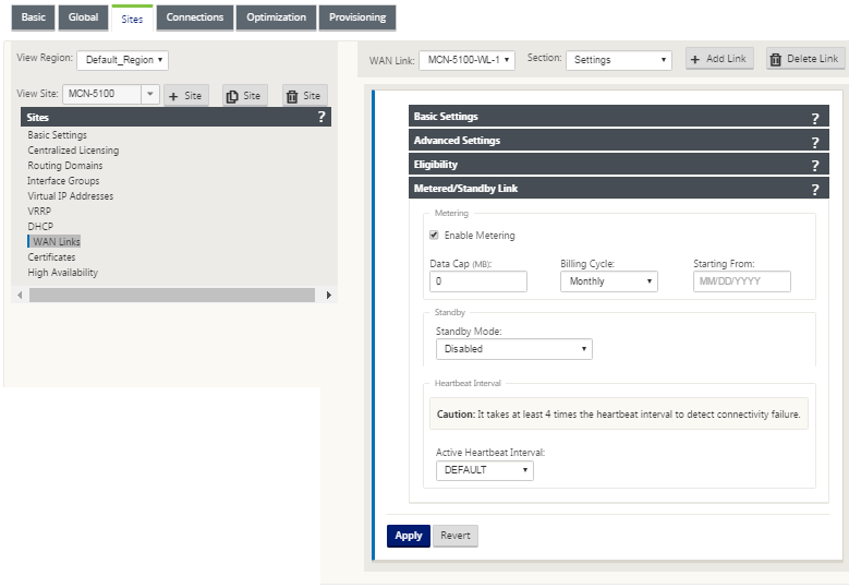
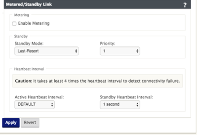
In the SD-WAN web management interface, navigate to Configuration Editor > Sites > WAN Links > Settings. Click Metered/Standby Link to expand it.
-
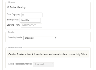
Check the Enable Metering checkbox. You can provide values for data cap, billing frequency, billing cycle start date, and the active heartbeat interval.
To configure standby links:
-
In the SD-WAN web management interface, navigate to Configuration Editor > Sites > WAN Links > Settings. Click Metered/Standby Link to expand it.
-
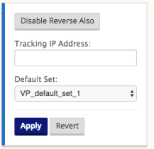
By default, standby mode of a WAN link is disabled. To configure the WAN link as standby, click the pencil icon next to Settings to enter edit mode and select one of the standby modes.
-
Once a standby mode is selected, select the standby priority, active heartbeat interval, and standby heartbeat interval as appropriate. Click apply to validate the configuration.
-
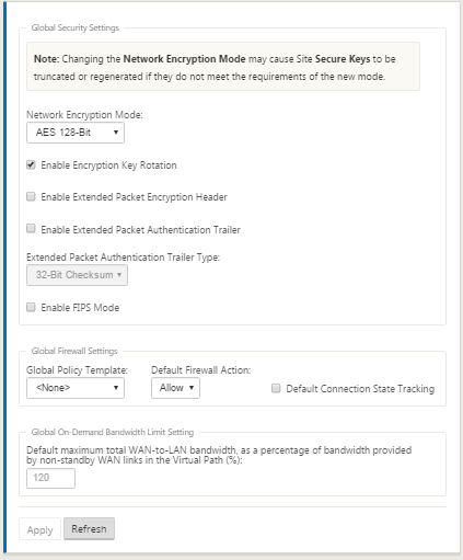
If an on-demand standby link is configured, the global default on-demand bandwidth limit (120%) is applied to the Virtual Path. This specifies the maximum WAN-to-LAN bandwidth allowed for the Virtual Path. It is expressed as a percentage of the total bandwidth provided by all non-standby links in the Virtual Path. As long as the available bandwidth in the Virtual Path is below the limit and if there is sufficient usage, the appliance attempts to activate on-demand paths to supplement bandwidth.
-
To view or change the global default on-demand bandwidth limit, open the sections Global > Virtual WAN Network Settings.
-
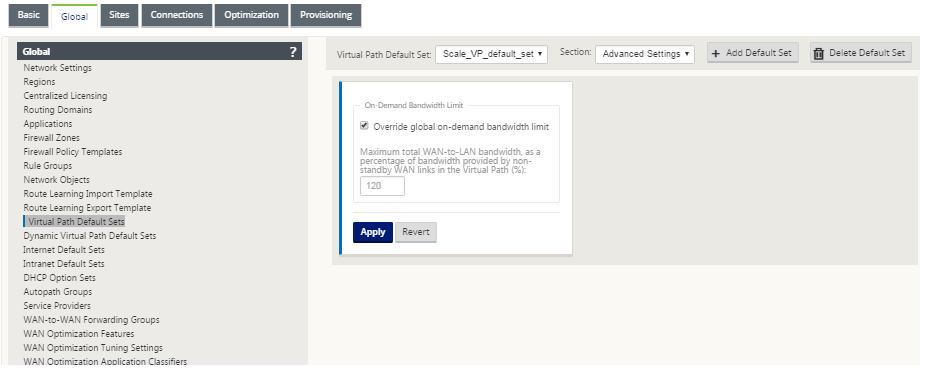
If you want to apply an on-demand bandwidth limit specific to a Virtual Path and keep the global default setting unchanged, a Virtual Path Default Set needs to be created and the on-demand bandwidth limit in the Advanced Settings can be changed.
-
To apply settings for a specific Virtual Path, the user should navigate to the section Connections > Site > Virtual Paths > Basic Settings and select the default set for the particular Virtual Path.
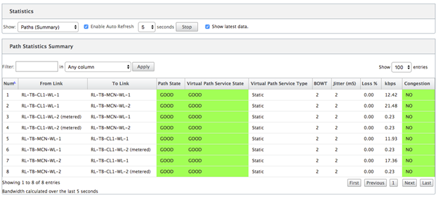
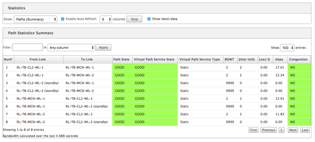
How To Monitor Metered and Standby WAN Links
-
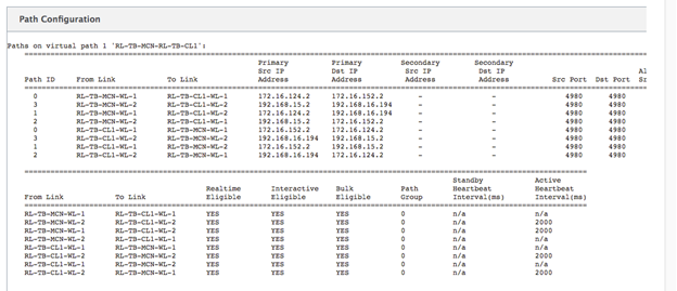
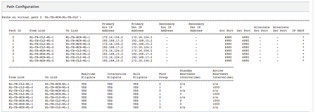
When path statistics (Monitoring > Statistics > Paths) are displayed, metered links and standby links are marked as shown below.
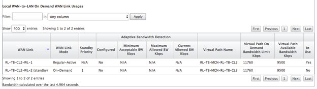
-
If the appliance has a Virtual Path that has a local or remote on-demand standby link, when WAN link usage statistics are viewed, an extra table showing on-demand bandwidth is displayed at the bottom of the page (Monitoring > Statistics > WAN Link Usage).
-
When the usage on a metered link exceeds 50% of the configured data cap, a warning banner is displayed across the top of the dashboard. In addition, if the usage exceeds 75% of the configured data cap, the numerical metering information toward the bottom of the dashboard is highlighted.
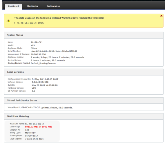 A WAN link usage event is also generated at the appliance when the usage exceeds 50%, 75%, and 90% of the configured data cap.
-
When a standby path transitions between standby and active state, an event is generated by the appliance.
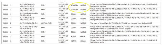
-
The configured active and standby heartbeat intervals for each path can be viewed at Configuration > Virtual WAN > View Configuration > Paths.