Site configuration
You can add new sites from the Network Home page or from the Profiles & Templates section to configure your SD-WAN network.
To create a site, click + New site on the Network Dashboard. Provide a name and location for the site.
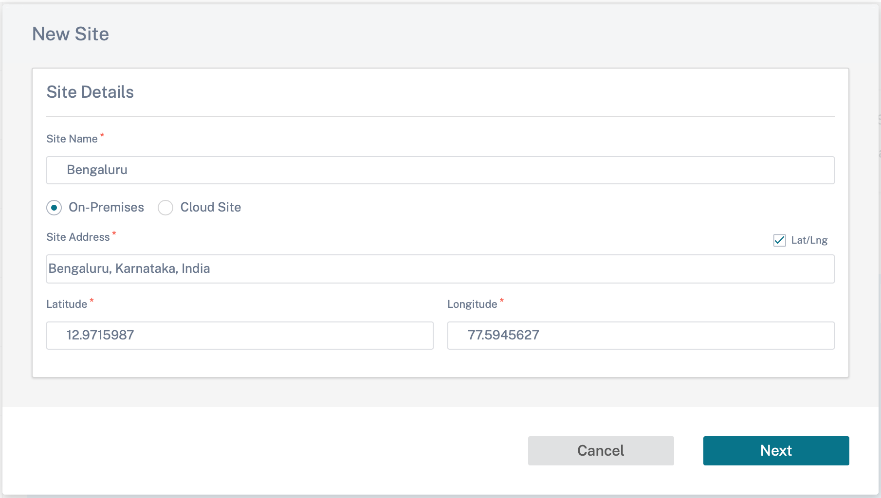
You can create a site from scratch, or use a site profile to configure a site quickly.
A graphical display to the right of the screen provides a dynamic topology diagram as you proceed with the configuration.
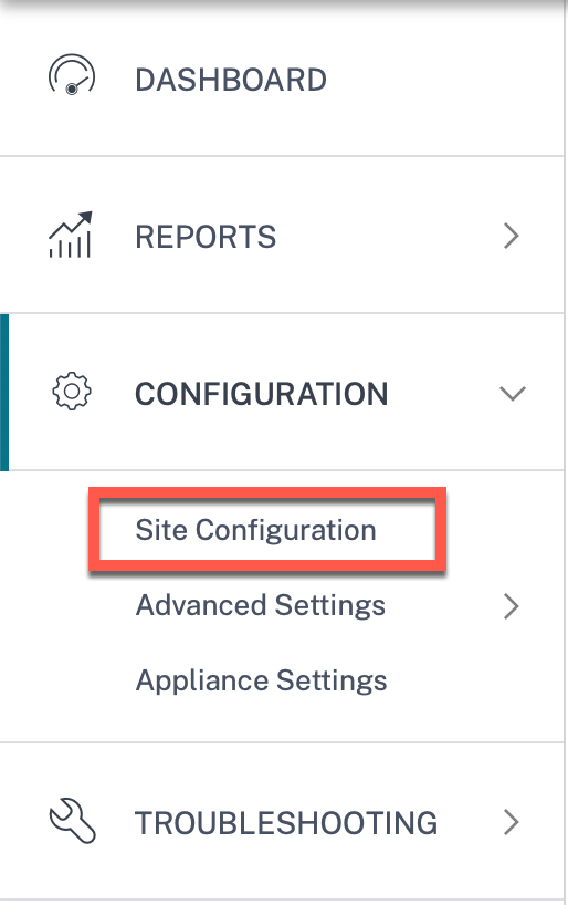
To view site configuration, select site and navigate to Configuration > Site Configuration.
Site details
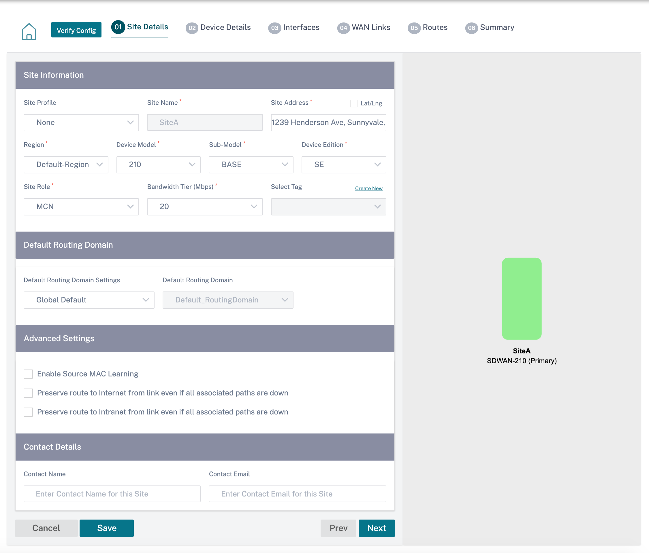
The first step involves entering the site, device, advanced settings, and site contact details.
When you configure sites using a site template, the following screen is displayed.
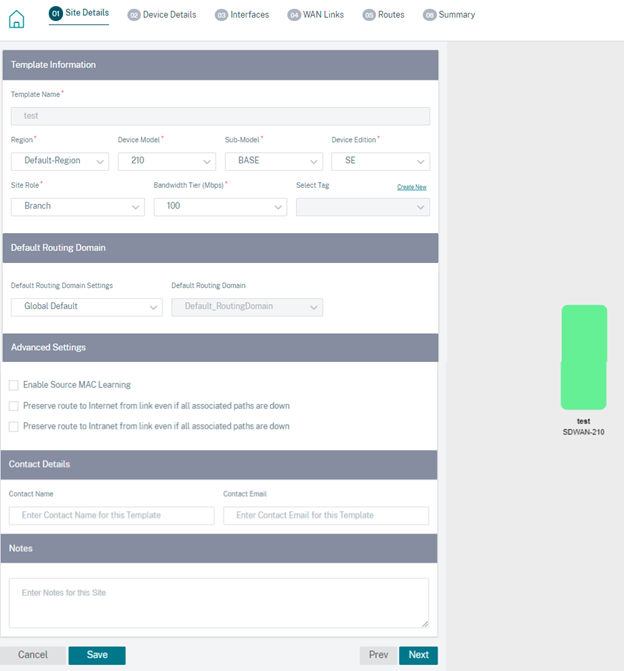
Site/Template information
- Choosing a Site Profile auto-populates the site, interface, and WAN links parameters based on the site profile configuration.
- Site Address and Site Name are auto-populated based on the details provided in the previous step.
- Enable the Lat/Lng check box to get the latitude and longitude of a site.
- Select the Region from the drop-down list.
- Device Model and Sub-Model can be picked based on the hardware model or virtual appliance used at a given site.
-
Device Edition reflects automatically based on the selected device model. Currently, Premium Edition (PE), Advanced Edition (AE), and Standard Edition (SE) are supported. The PE model is only supported on 1100, 2100, 5100, and 6100 platforms. The AE model is supported on 210 and 1100 platforms.
Note
Citrix SD-WAN Orchestrator for On-premises does not support Advanced Edition and Premium Edition platforms.
-
Site Role defines the role of the device. You can assign one of the following roles to a site:
- MCN: Master Control Node (MCN) serves as the controller of the network, and only one active device in a network can be designated as the MCN.
- Branch: Appliances at the branch sites that receive configuration from the MCN and participate in establishing virtual WAN functionalities to the branch offices. There can be multiple branch sites.
- RCN: Regional Control Node (RCN) supports hierarchical network architecture, enabling multi-region network deployment. MCN controls multiple RCNs and each RCN, in turn, controls multiple branch sites.
- Geo-redundant MCN: A site in a different location, that takes over the management functions of the MCN, if it is not available, ensuring disaster recovery. The geo-redundant MCN does not provide High Availability or failover capabilities for the MCN.
- Geo-Redundant RCN: A site in a different location, that takes over the management functions of the RCN, if it is not available, ensuring disaster recovery. The geo-redundant RCN does not provide High Availability or failover capabilities for the RCN.
- Bandwidth Tier is the billable bandwidth capacity you can configure on any device, depending on the device model. For instance, the SD-WAN 410 Standard Edition (SE) appliance supports 20, 50, 100, 150, and 200 Mbps bandwidth tiers. Depending on your bandwidth needs for a given site, you can select the desired tier. Each site is billed for the configured bandwidth tier.
Routing domain
The Routing Domain section allows you to select the default routing domain for the site. Routing Domain settings can either be global or site specific. If you select Global Defaults, the default routing domain that is applicable globally is auto-selected. If you select Site Specific, you can select the default routing domain from the Routing Domain drop-down list.
Routing support for LAN segmentation
The SD-WAN Standard and Enterprise Edition (SE/PE) appliances implement LAN segmentation across distinct sites where either appliance is deployed. The appliances recognize and maintain a record of the LAN side VLANs available, and configure rules around what other LAN segments (VLANs) can connect to at a remote location with another SD-WAN SE/PE appliance.
The above capability is implemented by using a Virtual Routing and Forwarding (VRF) table that is maintained in the SD-WAN SE/PE appliance, which keeps track of the remote IP address ranges accessible to a local LAN segment. This VLAN-to-VLAN traffic would still traverse the WAN through the same pre-established Virtual Path between the two appliances (no new paths need to be created).
An example use case for this functionality is that a WAN administrator might be able to segment local branch networking environment through a VLAN, and provide some of those segments (VLANs) access to DC-side LAN segments that have access to the internet, while others might not obtain such access. The configuration of the VLAN-to-VLAN associations is achieved through the Citrix SD-WAN Orchestrator for On-premises web interface.
Advanced settings
-
Enable Source MAC Learning: Stores the source MAC address of received packets so that outgoing packets to the same destination can be sent to the same port.
-
Preserve route to Internet from link even if all associated paths are down: When enabled, the packets destined for the internet service continue to choose the internet service even if all WAN Links for the internet service are unavailable.
-
Preserve route to Intranet from link even if all associated paths are down: When enabled, the packets destined for the intranet service continue to choose the intranet service even if all WAN Links for the intranet service are unavailable.
-
Contact details of the admin available at the site.
A dynamic network diagram to the right of the configuration panel, provides visual feedback on an ongoing basis, as you go through the configuration process.
Device details
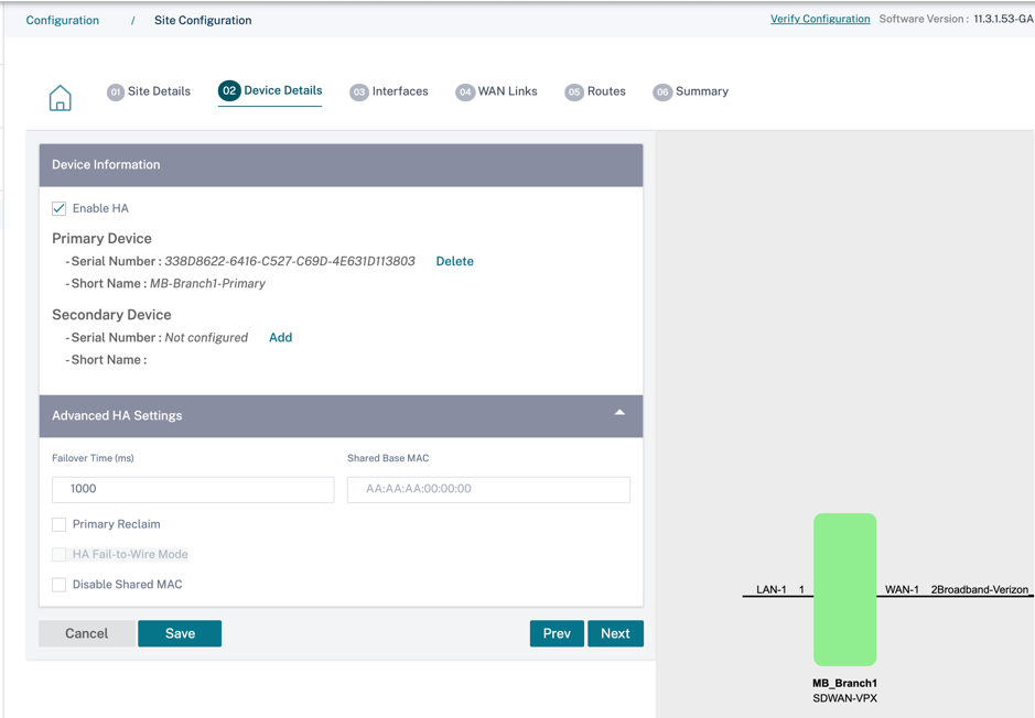
The device details section allows you to configure and enable High Availability (HA) at a site. With HA, two appliances can be deployed at a site as an active primary and a passive secondary. The secondary appliance takes over when the primary fails. For more information, see High Availability.
Note
Serial numbers are not configurable using the site templates.
Device information
Enable HA and enter the serial number and a short name for the primary and the secondary appliances. Click Add and provide the serial number along with the site short name.
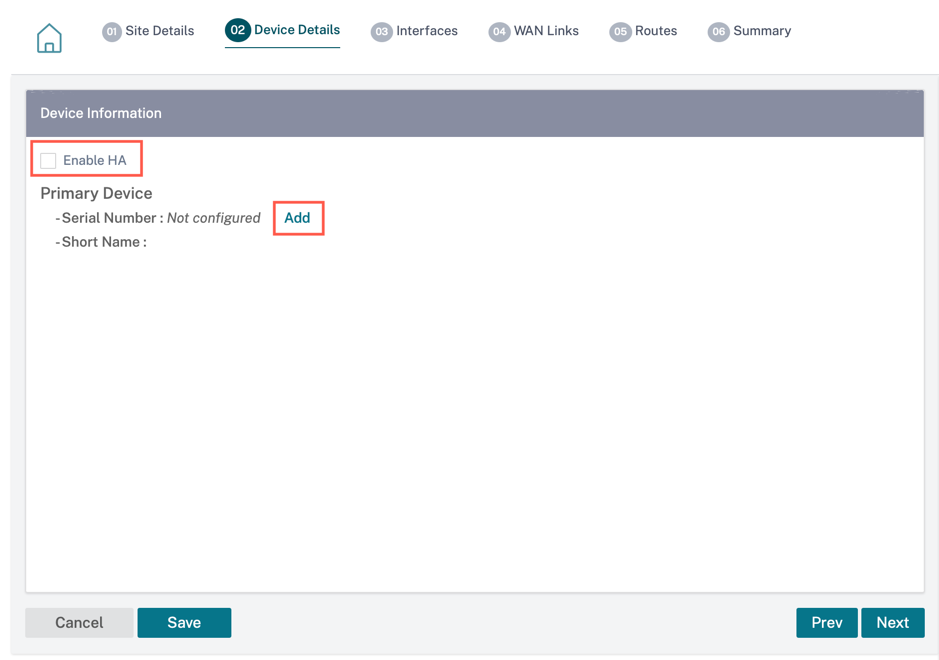
Click Add.
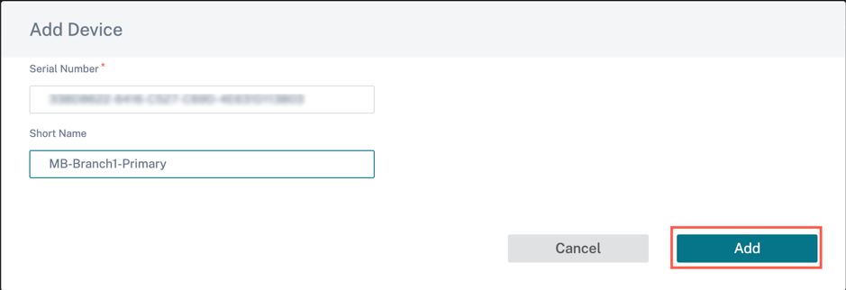
-
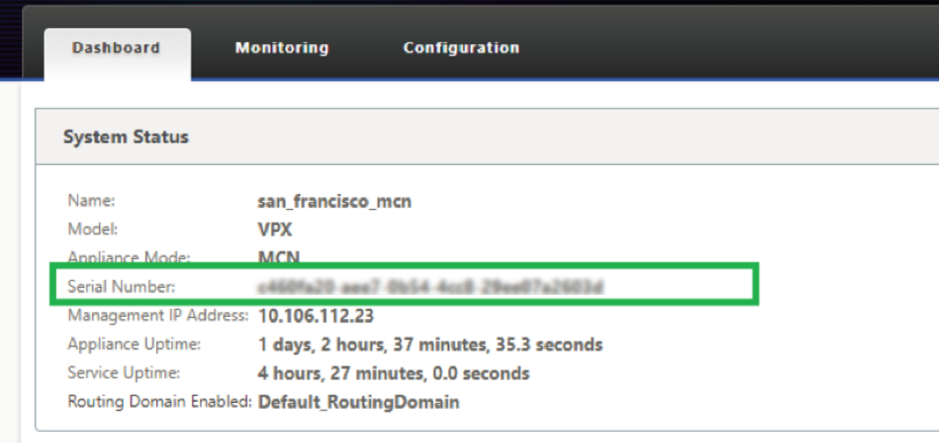
Serial Number: The Serial Number of a virtual SD-WAN instance (VPX) can be accessed from the VPX web console, as highlighted in the following screen shot. A serial number of a hardware appliance can be found on the device label too.
-
Short Name: The Short Name field is used to specify an easily identifiable short name for a site or to tag a site if desired.
Click the Delete option if you want to delete the serial number.
Note Updating serial number requires deleting the existing serial number and readding a new one.
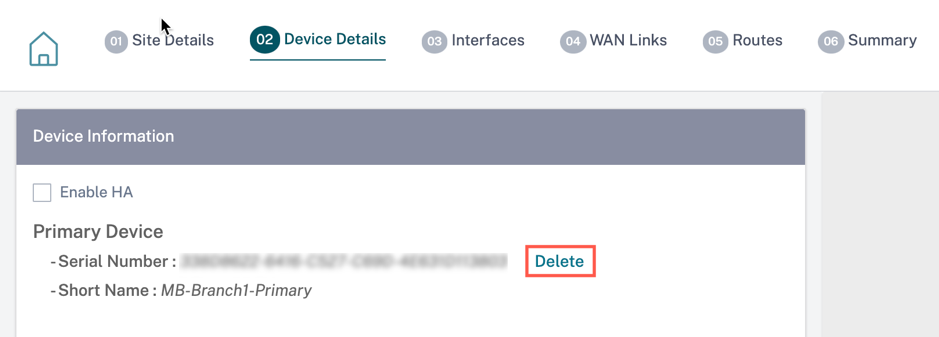
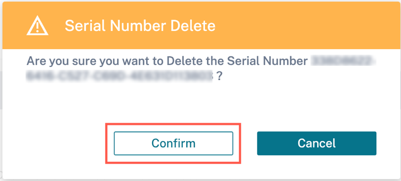
On clicking the Delete option, a pop-up appears to confirm if you want to delete the serial number or not.
Advanced HA settings
- Failover Time (ms): The wait time after contact with the primary appliance is lost, before the standby appliance becomes active.
- Shared base MAC: The shared MAC address for the high availability pair appliances. When a failover occurs, the secondary appliance has the same virtual MAC addresses as the failed primary appliance.
- Disable Shared Base MAC: This option is available on hypervisor and cloud-based platforms only. Choose this option to disable the shared virtual MAC address.
- Primary Reclaim: The designated primary appliance reclaims control upon restart after a failover event.
- HA Fail-to-Wire Mode: The HA Fail-to-wire mode is enabled. For more details, see HA deployment modes.
- Enable Y-Cable Support: The Small Form-factor Pluggable (SFP) ports can be used with a fiber optic Y-Cable to enable the high availability feature for Edge Mode deployment. This option is available on Citrix SD-WAN 1100 SE/PE appliances only. For more information, see Enable Edge Mode High Availability Using Fiber Optic Y-Cable.
Wi-Fi details
You can configure a Citrix SD-WAN™ appliance that supports Wi-Fi as a Wi-Fi Access Point.
The following two variants of Citrix SD-WAN 110 platform support Wi-Fi and can be configured as a Wi-Fi access point:
- Citrix SD-WAN 110-WiFi-SE
- Citrix SD-WAN 110-LTE-WiFi
For more details on Wi-Fi configuration, see Wi-Fi Access Point
Interfaces
The next step is to add and configure the interfaces. Click + Interface to start configuring the interface. Click + HA Interface to start configuring HA interface. The + HA Interface option is available only if you have configured a secondary appliance for high availability.
Interface configuration involves selecting the deployment mode and setting the interface level attributes. This configuration is applicable to both LAN and WAN links.
In-band management
In-band management allows you to use the SD-WAN data ports for management. It carries both data and management traffic, without having to configure an extra management path. In-band management allows virtual IP addresses to connect to management services such as web UI and SSH. You can access the web UI and SSH using the management IP and in-band virtual IPs.
To enable in-band management, choose an IPv4 address from the InBand Management IP drop-down list or an IPv6 address from the InBand Management IPv6 drop-down list. Select the DNS proxy to which all DNS requests over the in-band and backup management plane is forwarded to from the InBand Management DNS or InBand Management DNS V6 drop-down list.
For more information on in-band management, see In-band management.
The IP addresses configured for interfaces get listed under the InBand Management IP drop-down list. The DNS proxy services configured under Advanced Settings > DNS get listed in the InBand Management DNS drop-down list.
Interface attributes
The following deployment modes are supported:
- Edge (Gateway)
- Inline – Fail-to-wire, Fail-to-block, and Virtual inline.
-
Deployment Mode: Select one of the following deployment modes.
-
Edge (Gateway):

Gateway Mode implies SD-WAN serves as the “gateway” to the WAN for all the LAN traffic. The Gateway Mode is the default mode. You can deploy the appliance as a gateway on the LAN side or the WAN side.
-
Inline:
When SD-WAN is deployed in-line between a LAN switch and a WAN router, SD-WAN is expected to “bridge” LAN and WAN.
All the Citrix SD-WAN appliances have pre-defined bridge-paired interfaces. With the Bridge option enabled, selection of any interface on the LAN end automatically highlights the paired interface that is reserved for the WAN end of the bridge. For example, physical interfaces 1 and 2 are a bridged pair.
- Fail-To-Wire: Enables a physical connection between the bridged pair of interfaces, allowing traffic to bypass SD-WAN and flow directly across the bridge in the event of appliance restart or failure.
Earlier, the DHCP client was only supported on Fail-to-block port. With the Citrix SD-WAN 11.2.0 release, the DHCP client capability is extended on fail-to-wire port for the branch site with serial High Availability (HA) deployments. This enhancement:
- Allows the DHCP client configuration on untrusted interface group that has fail-to-wire bridge pair and serial HA deployments.
- Allows DHCP interfaces to be selected as part of Private Intranet WAN links.
Notes
- Inline (Fail-to-Wire) option is available only on hardware appliances and not on virtual appliances (VPX / VPXL).
- DHCP client is now supported on the private intranet link.
- A LAN interface must not be connected into the fail-to-wire pair as packets might be bridged between the interfaces.
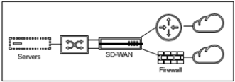
- Fail-to-Block: This option disables the physical connection between the bridged pair of interfaces on hardware appliances, preventing traffic from flowing across the bridge in the event of appliance restart or failure.
Note
Inline (Fail-to-Block) is the only bridge mode option available on virtual appliances (VPX / VPXL).
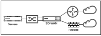
- Virtual Inline (One-Arm):
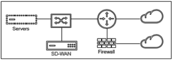
When SD-WAN is deployed in this mode, it has a single arm connecting it to the WAN router, LAN, and WAN sharing the same interface on SD-WAN. Therefore, the interface settings are shared between the LAN and WAN links.
-
- Interface Type: Select the interface type from the drop-down list.
- Security (Trusted / Untrusted): Specifies the security level of the interface. Trusted segments are protected by a Firewall.
- Interface Name: Based on the selected deployment mode, the Interface Name field is auto filled.
Physical interface
- Select Interface: Select the configurable Ethernet port that is available on the appliance.
Virtual interface
- VLAN ID: The ID for identifying and marking traffic to and from the interface.
- Virtual Interface Name: Based on the selected deployment mode, the Virtual Interface Name field is auto filled.
- Enable HA Heartbeat: Enable syncing of HA heartbeats over this interface. This option is enabled if you have configured a secondary appliance for HA. Select this option to allow primary and secondary appliances to synchronize the HA heartbeats over this interface. Specify the IP address of the primary and secondary appliance.
- Routing Domain: The routing domain that provides a single point of administration of the branch office network, or a data center network.
- Firewall Zones: The firewall zone to which the interface belongs. Firewall zones secure and control the interfaces in the logical zone.
-
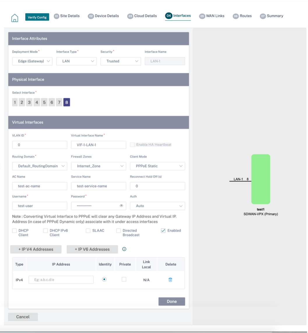
Client Mode: Select Client Mode from the drop-down list. On selection of PPPoE Static displays more settings.
Note
When the Site mode (under Site Details tab) is selected as Branch and the Security field (under Interface tab) is selected as Untrusted, the PPPoE Dynamic option is available under Client Mode.
Citrix SD-WAN acts as a PPPoE client. For IPv4, SD-WAN obtains the dynamic IPv4 address or uses the static IPv4 address. For IPv6, it obtains the link local address from the PPPoE server. For the IPv6 unicast address, Static IP, DHCP, or SLAAC can be used.
- DHCP Client: When enabled on the virtual interfaces, the DHCP Server assigns dynamically IPv4 addresses to the connected client.
- DHCP IPv6 Client: When enabled on the virtual interfaces, the DHCP Server dynamically assigns IPv6 addresses to the connected client.
- SLAAC: This option is available only for IPv6 addresses. When selected, the interface obtains IPv6 addresses through Stateless Address Auto-configuration (SLAAC).
- Directed Broadcast: When the Directed Broadcast check box is selected, the directed broadcasts are sent to the virtual IP subnets on the virtual interface.
-
Enabled: By default, the Enabled check box is selected for all virtual interfaces. If you want to disable the virtual interface, clear the Enabled check box.
Note
- The Enabled check box is available only from Citrix SD-WAN release 11.3.1 onwards.
- The option to disable a virtual interface is only available when it is not used by a WAN Link Access Interface. If the virtual interface is used by a WAN Link Access Interface, then the check box is read-only and selected by default.
- While configuring other features, along with enabled virtual interfaces, the disabled virtual interfaces also get listed, except under Access Interfaces for a WAN Link. Even if you select a disabled virtual interface, the virtual interface is not considered and does not impact the network configuration.
- + IPv4 Address: The virtual IPv4 address and netmask of the interface.
- + IPv6 Address: The virtual IPv6 address and prefix of the interface.
- Identity: Choose an identity to be used for IP services. For example, Identity is used as the Source IP Address to communicate with BGP neighbors.
- Private: When enabled, the Virtual IP Address is only routable on the local appliance.
Note
- LTE ports do not support static IP addresses (IPv4 and IPv6).
- LTE ports support both DHCP and SLAAC. Configuring DHCPv4 or DHCPv6 is mandatory. SLAAC is optional.
- In LTE ports, Link-Local addresses can be configured for IPv6 or SLAAC.
PPPoE credentials
Point-to-Point Protocol over Ethernet (PPPoE) connects multiple computer users on an Ethernet LAN to a remote site through common customer premises appliances, for example; Citrix SD-WAN. PPPoE allows users to share a common Digital Subscriber Line (DSL), cable modem, or wireless connection to the Internet. PPPoE combines the Point-to-Point Protocol (PPP), commonly used in dialup connections, with the Ethernet protocol, which supports multiple users in a LAN. The PPP protocol information is encapsulated within an Ethernet frame.
Citrix SD-WAN appliances use PPPoE to support ISP to have ongoing and continuous DSL and cable modem connections unlike dialup connections. PPPoE provides each user-remote site session to learn each other’s network addresses through an initial exchange called “discovery”. After a session is established between an individual user and the remote site, for example, an ISP provider, the session can be monitored. Corporations use shared Internet access over DSL lines using Ethernet and PPPoE.
Citrix SD-WAN acts as a PPPoE client. For IPv4, SD-WAN obtains the dynamic IPv4 address or uses the static IPv4 address. For IPv6, it obtains the link local address from the PPPoE server. For the IPv6 unicast address, Static IP, DHCP, or SLAAC can be used.
The following is required to establish successful PPPoE sessions:
- Configure virtual network interface (VNI).
- Unique credentials for creating PPPoE session.
- Configure WAN link. Each VNI can have only one WAN link configured.
- Configure Virtual IP address. Each session obtains a unique IP address, dynamic, or static, based on the provided configuration.
- Deploy the appliance in bridge mode to use PPPoE with static IP address and configure the interface as “trusted.”
- Static IP is preferred to have a configuration to force the server proposed IP; if different from the configured static IP, an error can occur.
- Deploy the appliance as an Edge device to use PPPoE with dynamic IP and configure the interface as “untrusted.”
- Authentication protocols supported are, PAP, CHAP, EAP-MD5, EAP-SRP.
- Maximum number of multiple sessions depends on the number of VNIs configured.
- Create multiple VNIs to support Multiple PPPoE sessions per interface group.
Note
Multiple VNIs are allowed to create with the same 802.1Q VLAN tag.
Limitations for PPPoE configuration:
- 802.1q VLAN tagging is not supported.
- EAP-TLS authentication is not supported.
- Address/Control compression.
- Deflate Compression.
- Protocol field compression negotiation.
- Compression Control Protocol.
- BSD Compress Compression.
- IPX protocols.
- PPP Multi Link.
- Van Jacobson style TCP/IP header compression.
- Connection-ID compression option in Van Jacobson style TCP/IP header compression.
- PPPoE is not supported on LTE interfaces.
From Citrix SD-WAN 11.3.1 release, an extra 8 bytes PPPoE header is considered for adjusting TCP Maximum Segment Size (MSS). The extra 8 bytes PPPoE header adjusts the MSS in the synchronize packets based on the MTU. The supported MTU ranges from 1280 bytes to 1492 bytes.
PPPoE configuration
On an MCN, you can configure only PPPoE static. On a branch, you can configure either PPPoE static or PPPoE dynamic.
To configure PPPoE, at the site level configuration, navigate to Configuration > Site Configuration > Interfaces tab. In the Virtual Interfaces section, select the appropriate PPPoE option from the Client Mode drop-down list.
Note
- A VNI configured with multiple interfaces can have only one interface used for PPPoE connectivity.
- If a VNI configured with multiple interfaces and a PPPoE connectivity is changed to a different interface, then the Reports > Real Time > PPPoE page can be used to stop the existing session and start a new session. The new session can then be established over the new interface.
- If PPPoE Dynamic is selected, the VNI is required to be “Untrusted.”
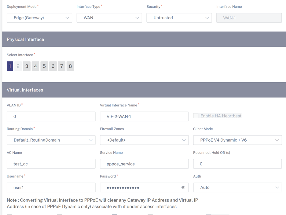
- AC Name: Provide the Access Concentrator (AC) name for the PPPoE configuration.
- Service Name: Enter a service name.
- Reconnect Hold Off (s): Enter the reconnect attempt hold off time.
- User Name: Enter the user name for the PPPoE configuration.
- Password: Enter the password for the PPPoE configuration.
-
Auth: Select the authorization protocol from the drop-down list.
- When the Auth option is set to Auto, the SD-WAN appliance honors the supported authentication protocol request received from the server.
- When the Auth option is set to PAP/CHAP/EAP, then only specific authentication protocols are honored. If PAP is in the configuration and the server sends an authentication request with CHAP, the connection request is rejected. If the server does not negotiate with PAP, an authentication failure occurs.
Only one WAN link creation is allowed per PPPoE static or dynamic VNI. The WAN link configuration varies depending on the VNI selection of the Client Mode.
If the VNI is configured with PPPoE dynamic client mode:
- IP address and Gateway IP address fields become inactive.
- Virtual path mode is set to “Primary.”
- Proxy ARP cannot be configured.
By default, Gateway MAC Address Binding is selected.
If the VNI is configured with PPPoE static client mode, then configure the IP address.
Note
If the server does not honor the configured static IP address and offers a different IP address, an error occurs. The PPPoE session tries to re-establish connection periodically, until the server accepts the configured IP address.
PPPoE Monitoring and Troubleshooting
At the site level, navigate the Reports > Real Time > PPPoE section to view information about the configured VNIs with the PPPoE static or dynamic client mode. It allows you to manually start or stop the sessions for troubleshooting purposes.

When there is a problem in establishing a PPPoE session:
- Hovering the mouse over the failed status shows the reason for the recent failure.
- To establish a fresh session or for troubleshooting an active PPPoE session, restart the session.
- If a PPPoE session is stopped manually, it cannot be started until either it is manually started and a configuration change is activated, or the service is restarted.
A PPPoE session might fail due to the following reasons:
- When SD-WAN fails to authenticate itself to the peer due to an incorrect username/password in the configuration.
- PPP negotiation fails - negotiation does not reach the point where at least one network protocol is running.
- System memory or system resource issue.
- Invalid/bad configuration (wrong AC name or service name).
- Failed to open serial port due to operating system error.
- No response received for the echo packets (link is bad or the server is not responding).
- There were several continuous unsuccessful dialing sessions with in a minute.
After 10 consecutive failures, the reason for the failure is observed.
- If the failure is normal, it restarts immediately.
- If the failure is an error then restart reverts for 10 seconds.
- If the failure is fatal the restart reverts for 30 seconds before restarting.
LCP Echo request packets are generated from SD-WAN for every 60 seconds and failure to receive 5 echo responses is considered as link failure and it re-establishes the session.
- If the VNI is up and ready, the IP and Gateway IP columns shows the current values in the session. It indicates that these are recently received values.
- If the VNI is stopped or is in failed state, the values are the last received values.
- Hovering the mouse over the Gateway IP column shows the MAC address of the PPPoE Access Concentrator from where the Session and IP is received.
- Hovering the mouse over the “state” value shows a message, which is more useful for a “Failed” state.
| PPPoE session type | Status Color | Description |
|---|---|---|
| Configured | Yellow | A VNI is configured with PPPoE. This is an initial state. |
| Dialing | Yellow | After a VNI is configured, the PPPoE session state moves to dialing state by starting the PPPoE discovery. Packet information is captured. |
| Session | Yellow | VNI is moved from Discovery state to Session state, waiting to receive IP, if dynamic or waiting for acknowledgment from the server for the advertised IP, if static. |
| Ready | Green | IP packets are received and the VNI and associated WAN link is ready for use. |
| Failed | Red | PPP/PPPoE session is terminated. The reason for the failure can be due to invalid configuration or fatal error. The session attempts to reconnect after 30 seconds. |
| Stopped | Yellow | PPP/PPPoE session is manually stopped. |
| Terminating | Yellow | An intermediate state terminating due to a reason. This state automatically starts after certain duration (5 seconds for normal error or 30 secs for a fatal error). |
| Disabled | Yellow | The SD-WAN service is disabled. |
The SDWAN_ip_learned.log file contains logs related to PPPoE. Navigate to Troubleshooting > Device Logs to view or download the SDWAN_ip_learned.log file.
Wired 802.1X configuration
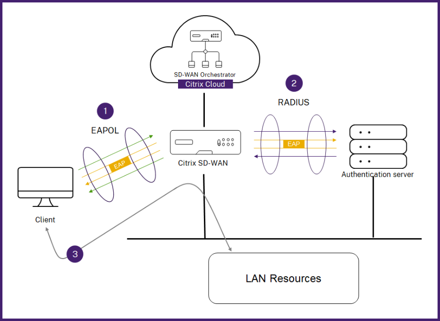
Wired 802.1X is an authentication mechanism that requires clients to authenticate before being able to access the LAN resources. Citrix SD-WAN Orchestrator for On-premises supports configuring wired 802.1X authentication on LAN interfaces.
In the Citrix SD-WAN network, the clients send authentication requests to the Citrix SD-WAN appliance to access the LAN resources. The Citrix SD-WAN appliance acts as an authenticator and sends the authentication requests to the authentication server. Citrix SD-WAN Orchestrator for On-premises supports only RADIUS servers to be configured as authentication servers.
When authenticating for the first time, only EAPOL packets can be processed or DHCP packets that can initialize the 802.1X authentication from the default virtual LAN. A newly connected client must be authenticated within 90 seconds. If the authentication is successful, it gets access to the LAN resources.
If the authentication fails, the client is not granted network access and all packets are dropped. The clients that are directly connected to the Citrix SD-WAN appliance can retry authentication by unplugging the Ethernet cable and reinserting it. Optionally, you can define a specific virtual LAN to grant access to limited LAN resources for the failed authentication requests. In such cases, the failed authentication requests get access to the specified virtual LAN. You can restrict access to the authenticated traffic using different routing domains or firewall zones while creating the virtual LAN.
Note
- The default virtual LAN must always have 802.1X enabled.
- Dynamic virtual LANs are not supported.
The Citrix SD-WAN appliance expects to receive packets without an 802.1Q tag (untagged packets). If the Citrix SD-WAN appliance receives a packet with an 802.1Q tag set to the assigned virtual LAN, then all the packets originated from the MAC must be tagged. If a packet is received with no 802.1Q tag in the header or with a tag other than the virtual LAN that the MAC address belongs to, then the packet is dropped.
When multiple clients connected to a switch try to authenticate at the same time over a single port, each client is authenticated individually, before it can gain access to the LAN resources. The clients that fail to authenticate can retry authentication by unplugging the Ethernet cable, waiting for 3 minutes, and reinserting the Ethernet cable. Citrix SD-WAN 110, 210, and 410 platforms support a maximum of 32 clients (both authenticated and unauthenticated). All other platforms support a maximum of 64 clients (both authenticated and unauthenticated).
To configure 802.1X authentication, navigate to Site Configuration > Interfaces and turn on the Enable 802.1x toggle button. Select an existing RADIUS profile or click Create RADIUS Profile to create a RADIUS profile. For details on creating a RADIUS profile, see RADIUS server profiles. You can use the same RADIUS profiles for wired 802.1x and wireless WPA2-enterprise authentication, provided your appliance supports wireless WPA2-enterprise.
Select a virtual interface from the Authenticated VIF drop-down list. The selected virtual interface grants access to the LAN resources for successful authentication requests.
Optionally, you can select an interface from the Unauthenticated VIF drop-down list. The selected virtual interface grants access to a specific LAN resource for the failed authenticated requests.
You can add a list of MAC addresses which bypasses the authentication process. Traffic from these MAC addresses will be implicitly treated as authenticated. These MAC addresses are susceptible to malicious attacks. So, use this capability only in physically secure environments and for legacy hardware that does not support wired 802.1x authentication.
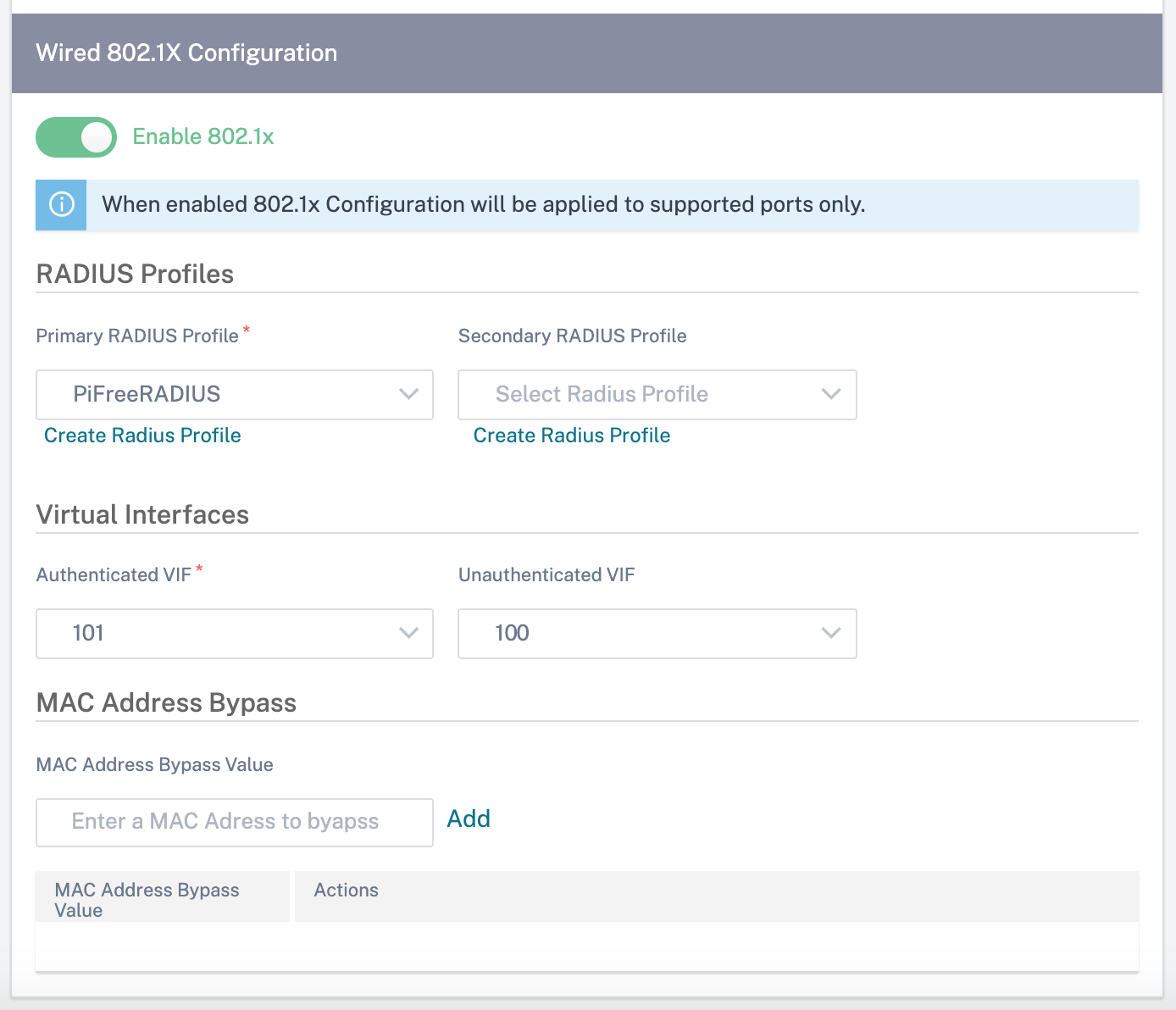
You can view the alerts associated with wired 802.1x authentication requests under Reports > Alerts. For more information, see Alerts.
WAN links
The next step is to configure WAN links. Click + WAN Link to start configuring a WAN link.
WAN link configuration involves setting up the WAN link access type and access interface attributes.
You can configure the WAN link attribute from scratch, or use a WAN link template to configure WAN link attributes quickly. If you have already used a site profile, the WAN link attributes auto-populate.
WAN link attributes
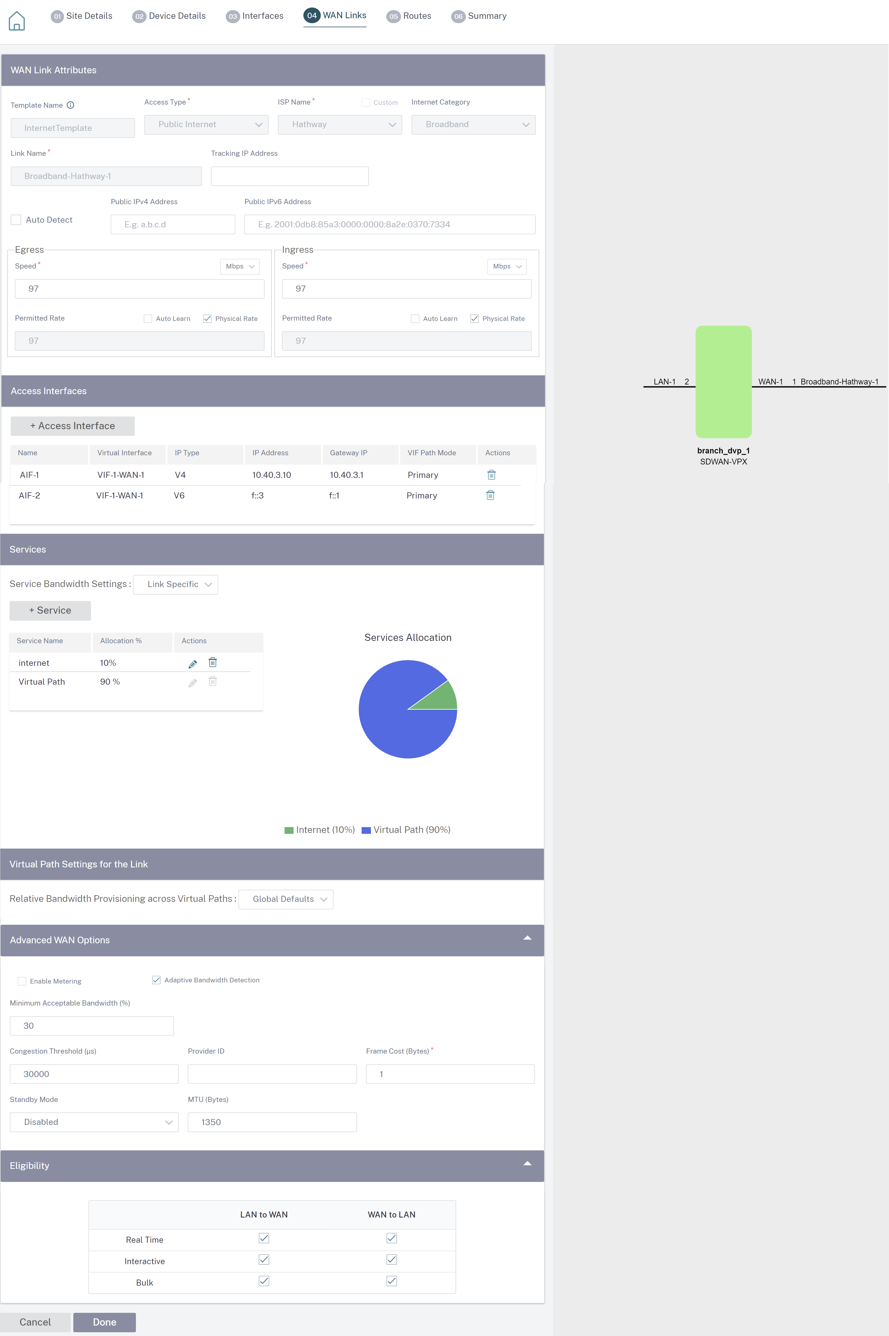
- Template Name: The name of the WAN link template used to create the WAN link. The WAN link template name cannot be modified after the creation of WAN links. Once WAN links are created using a WAN link template, you cannot edit the Access Type, ISP Name, or Internet Category.
-
Access Type: Specifies the WAN connection type of the link.
- Public Internet: Indicates that the link is connected to the Internet through an ISP.
- Private Intranet: Indicates that the link is connected to one or more sites within the SD-WAN network and cannot connect to locations outside the SD-WAN network.
- MPLS: Specialized variant of Private Intranet. Indicates the link uses one or more DSCP tags to control the Quality of Service between two or more points on an Intranet and cannot connect to locations outside of the SD-WAN network.
- ISP Name: The name of the service provider.
- Internet category: The type of WAN link Internet access technology service (Broadband, Satellite, Fiber, LTE, and so on) enabled on the WAN link.
- Link Name: Auto-populated based on the previous inputs.
- Tracking IP Address: The Virtual IP Address on the Virtual Path that can be pinged to determine the state of the path.
- Public IPv4 Address and Public IPv6 Address: The IP address of the NAT or DNS Server. This address is applicable and exposed, only when the WAN link access type is Public Internet or Private Intranet in Serial HA deployment. Public IP can either be manually configured or auto-learned using the Auto Learn option.
- Auto Detect: When enabled, the SD-WAN appliance automatically detects the public IP address. This option is available only when the device role is a branch and not the Master Control Node (MCN).
-
Egress Speed: The WAN to LAN speed.
- Speed: The available or allowed speed of the WAN to LAN traffic in Kbps or Mbps.
- Permitted Rate: In cases where the entire WAN link capacity is not supposed to be used by the SD-WAN appliance, change the permitted rate accordingly.
- Auto Learn: When you are unsure of the bandwidth and if the links are non-reliable, you can enable the Auto Learn feature. The Auto Learn feature learns the underlying link capacity only, and uses the same value in the future.
- Physical Rate: The actual bandwidth capacity of the WAN link.
-
Ingress Speed: The LAN to WAN speed.
- Speed: The available or allowed speed of the LAN to WAN traffic in Kbps or Mbps.
- Permitted Rate: In cases where the entire LAN link capacity is not supposed to be used by the SD-WAN appliance, change the permitted rate accordingly.
- Auto Learn: When you are unsure of the bandwidth and if the links are non-reliable, you can enable the Auto Learn feature. The Auto Learn feature learns the underlying link capacity only, and uses the same value in the future.
- Physical Rate: The actual bandwidth capacity of the LAN link.
MPLS Queues
The MPLS queue settings are available for WAN link access type MPLS only. This option is meant to enable definition of queues corresponding to the Service Provider MPLS queues, on the MPLS WAN Link. For information about adding MPLS queues, see MPLS queues.
Access Interface
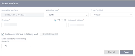
An Access Interface defines the IP Address and Gateway IP Address for a WAN Link. At least one Access Interface is required for each WAN Link. The following are the access interface parameters:
- Access Interface Name: The name by which Access interface is referenced. The default uses the following naming convention: WAN_link_name-AI-number: Where WAN_link_name is the name of the WAN link you are associating with this interface, and number is the number of Access Interfaces currently configured for this link, incremented by 1.
- Virtual Interface: The Virtual Interface that the Access Interface uses. Select an entry from the drop-down menu of Virtual Interfaces configured for the current branch site.
- Virtual Path Mode: Specifies the priority for Virtual Path traffic on the current WAN link. The options are: Primary, Secondary, or Exclude. If set to Exclude, the Access Interface is used for Internet and Intranet traffic, only.
- IP Address: The IP Address for the Access Interface endpoint from the appliance to the WAN. Select V4 (IPv4) or V6 (IPv6) as required.
- Gateway IP Address: The IP Address for the gateway router.
- Bind Access Interface to Gateway MAC: If enabled, the source MAC address of packets received on Internet or Intranet services must match the gateway MAC addressWANK links > Advances WAN Options.
- Enable Proxy ARP: If enabled, the Virtual WAN Appliance replies to ARP requests for the Gateway IP Address, when the gateway is unreachable.
- Enable Internet Access on Routing Domain(s): Auto-creates a DEFAULT route (0.0.0.0/0) in all the routing tables of the respective routing domains. You can enable for ALL routing domains or NONE. It avoids the need for creating exclusive static route across all the routing domains if they needed internet access.
Services
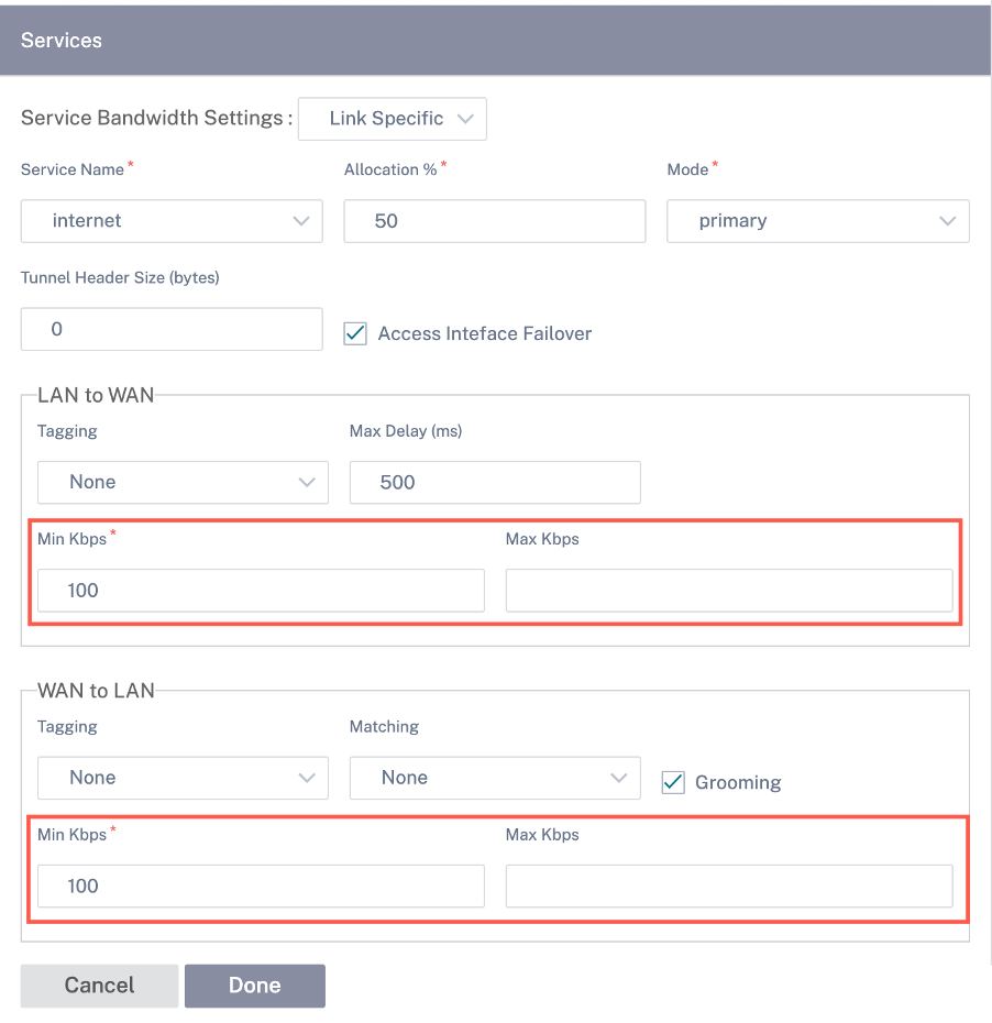
The Services section allows you to add service types and allocate the percentage of bandwidth to be used for each service type. You can define the service types and configure attributes for it from the Delivery services section. You can choose to use these global defaults or configure link specific service bandwidth settings from the Service Bandwidth Settings drop-down list. If you choose link specific, enter the following details:
- Service Name: The name of the WAN link service.
- Allocation %: The guaranteed fair share of bandwidth allocated to the service from the link’s total capacity.
- Mode: The operation mode of the WAN Link, based on the service selected. For Internet, there is one of Primary, Secondary, and Balance and for Intranet there is Primary and Secondary.
- Tunnel Header Size: The size of the tunnel header, in bytes.
- LAN to WAN Tag: The DHCP tag to apply to LAN to WAN packets on the service.
- LAN to WAN Delay: The maximum time, to buffer packets when the WAN Links bandwidth is exceeded.
- LAN to WAN Min Kbps: The minimum upload bandwidth value that is reserved for the service. The Min Kbps is a mandatory field.
- LAN to WAN Max Kbps: The maximum upload bandwidth value that is reserved for the service. The Max Kbps field is optional and the value cannot be lesser than the configured minimum upload bandwidth value. The value must be greater than or equal to the minimum upload bandwidth value.
- WAN to LAN Tag: The DHCP tag to apply to WAN to LAN packets on the service.
- WAN to LAN Match: The match criteria for Internet WAN to LAN packets to get assigned to the service.
- WAN to LAN Min Kbps: The minimum download bandwidth value that is reserved for the service. The Min Kbps is a mandatory field.
- WAN to LAN Max Kbps: The maximum download bandwidth value that is reserved for the service. The Max Kbps field is optional and the value cannot be lesser than the configured minimum download bandwidth value. The value must be greater than or equal to the minimum download bandwidth value.
- WAN to LAN Grooming: If enabled, packets are randomly discarded to prevent WAN to LAN traffic from exceeded the Service’s provisioned bandwidth.
Note
The minimum and maximum Kbps fields are not available for the Virtual Path.
Virtual Path settings for the link
Select the relative bandwidth provisioning across virtual paths as Global Default or Link Specific as required. On selecting Link Specific, when you enable the auto-bandwidth provisioning, the share of the bandwidth for the virtual path service is automatically calculated and applied accordingly to the magnitude of bandwidth that might be consumed by remote sites.
-
Max to Min Virtual Path Bandwidth Ratio for the Link: You can set the maximum to minimum virtual path ratio that can be applied to the selected WAN link.
-
Minimum Reserved Bandwidth for each Virtual Path (Kbps): You can set the minimum reserved bandwidth value in Kbps for each virtual path.
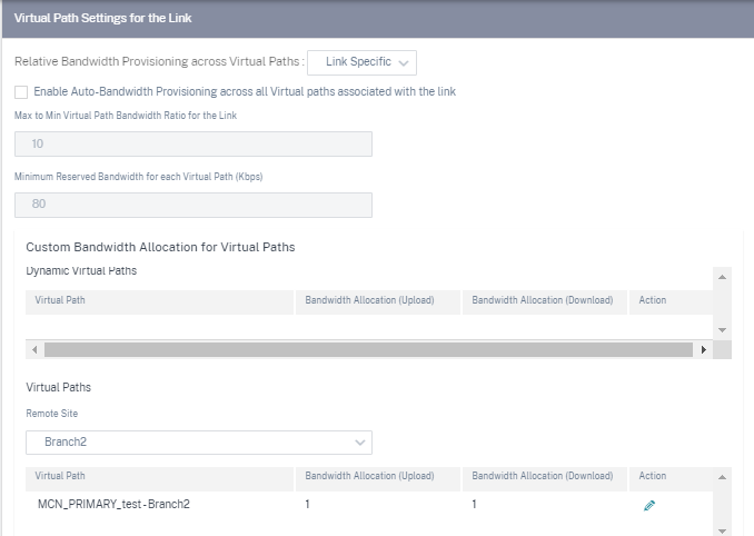
To customize the bandwidths for the virtual paths associated with a WAN link:
-
Clear the Enable Auto-Bandwidth Provisioning across all virtual paths associated with the link check box.
-
In the Custom Bandwidth Allocation for Virtual Paths section, select a remote site. You can provision bandwidths for the virtual paths to the remote site.
-
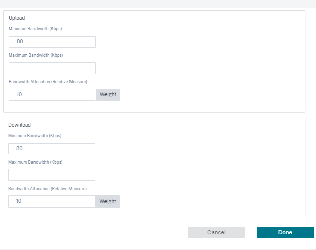
Minimum Bandwidth (Kbps): The minimum bandwidth reserved for the virtual path. The minimum bandwidth that you can set for a virtual path is 80 Kbps.
-
Maximum Bandwidth (Kbps): The maximum bandwidth that the virtual path can utilize from the WAN link. If the maximum bandwidth is not set, the site utilizes all of the available bandwidth.
-
Bandwidth Allocation (Relative Measure): The bandwidth share allocated to a virtual path out of its group’s eligible bandwidth. For example, if a WAN link group of 3 virtual paths is eligible for 30 Mbps bandwidth and you want to allocate equal bandwidth for each virtual path, update 10 as the bandwidth allocation on the remote site.
-
-
Click Done.
Note
Citrix SD-WAN Orchestrator for On-premises retains the previously configured custom bandwidth settings even after the previously configured dynamic virtual paths are disabled between two sites. Ensure to update the custom bandwidth settings manually when you reconfigure the dynamic virtual paths.
Points to consider for bandwidth provisioning
-
By default, all branches and WAN services (Virtual Path/Internet/Intranet) receive a weightage of 1 each.
-
Bandwidth customization is required when there is a high disparity in terms of bandwidth requirement.
-
When dynamic virtual paths are enabled between the available sites, the WAN link capacity is shared between the static virtual path to the data center and the dynamic virtual paths.
Advanced WAN options
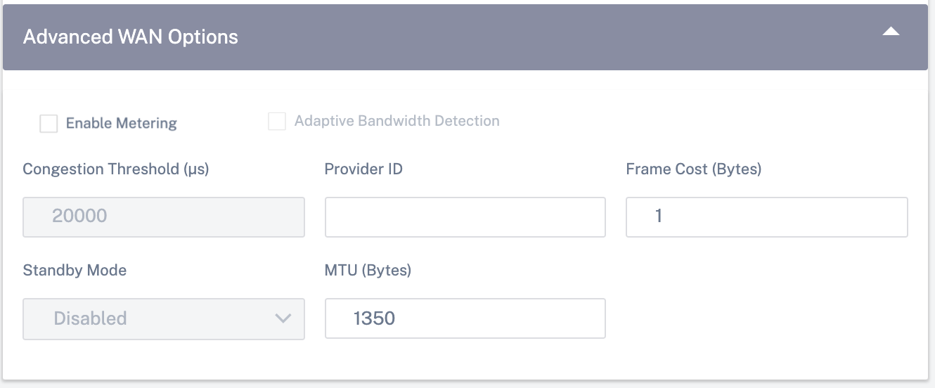
The WAN Link Advanced Settings allows the configuration of the ISP specific attributes.
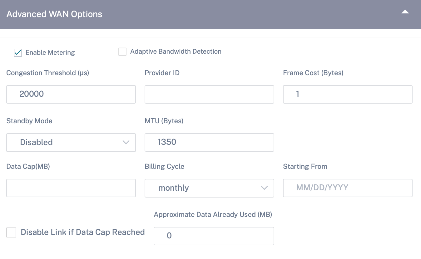
- Congestion Threshold: The amount of congestion after which the WAN link throttles packet transmission to avoid further congestion.
- Provider ID: Unique Identifier for the provider to differentiate paths when sending duplicate packets.
- Frame Cost (Bytes): Extra header/trailer bytes added to every packet, such as for Ethernet IPG or AAL5 trailers.
- MTU (Bytes): The largest raw packet size in bytes, not including the Frame Cost.
-
Standby Mode: A standby link is not used to carry user traffic unless it becomes active. The standby mode of a WAN link is disabled by default. For more information on standby mode, see Standby mode.
-
Enable Metering: Tracks usage on a WAN link and alerts the user when the link usage exceeds the configured data cap. For detailed information on metering, see Metering and Standby WAN Links.
-
Adaptive Bandwidth Detection: Uses the WAN link at a reduced bandwidth rate when a loss is detected. When the available bandwidth is below the configured Minimum Acceptable Bandwidth, then the path marked as BAD. Use Custom Bad Loss Sensitivity under Path or Autopath group with Adaptive Bandwidth Detection.
Note
Adaptive Bandwidth Detection is available only for Client and not for MCN.
- Minimum Acceptable Bandwidth: When there is varying bandwidth rate, the percentage of WAN to LAN permitted rate below which the path is marked as BAD. The minimum kbps is different on each side of a virtual path. The value can be in the range 10%-50% and the default being 30%.
For more information, see Adaptive bandwidth detection
Routes
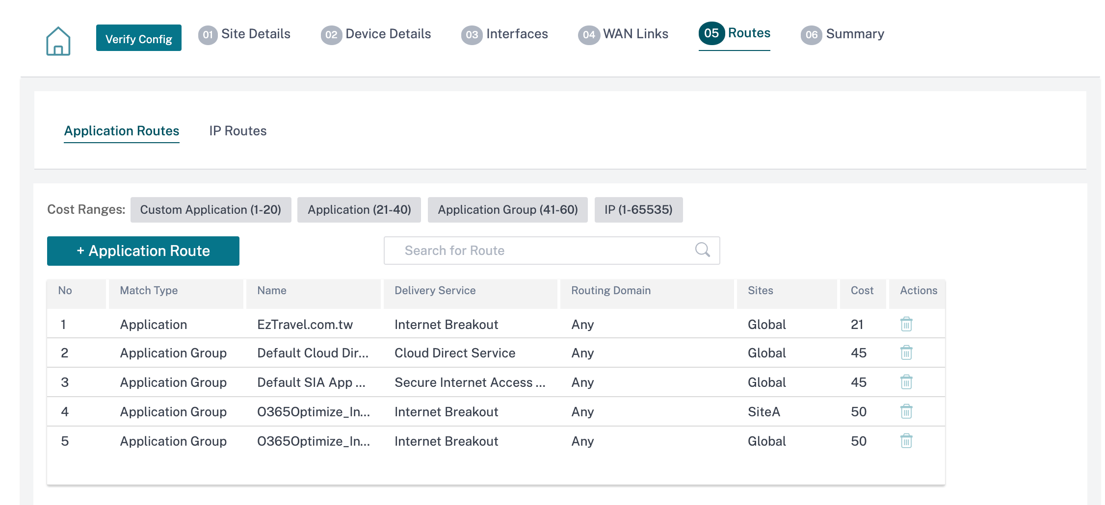
The next step in the site configuration workflow is to create routes. You can create application and IP routes based on your site requirements.
NOTE
The routes that were added before introducing the Application Route and IP Route tabs are listed under the IP Routes tab with Delivery Service as Internet.
The global routes and site-specific routes that are created at the network level automatically get listed under Routes > Application Routes and Routes > IP routes tabs. You can only view the global routes at the site level. To edit or delete a global route, navigate to network level configurations.
You can also create, edit, or delete routes at the site level.
Application routes
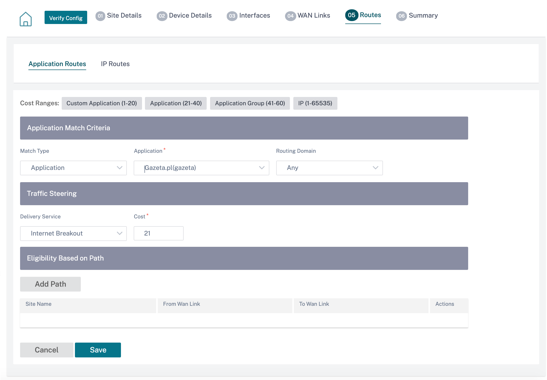
Click + Application Route to create an application route.
-
Custom Application Match Criteria:
- Match Type: Select the match type as Application/Custom Application/Application Group from the drop-down list.
- Application: Choose one application from the drop-down list.
- Routing Domain: Select a routing domain.
-
Traffic Steering
- Delivery Service: Choose one delivery service from the list.
- Cost: Reflects the relative priority of each route. Lower the cost, the higher the priority.
-
Eligibility Based on Path:
- Add Path: Choose a site and WAN links, both to and from. If the added path goes down, then the application route does not receive any traffic.
If a new application route gets added, then the route cost must be in the following range:
- Custom application: 1–20
- Application: 21–40
- Application group: 41–60
IP routes
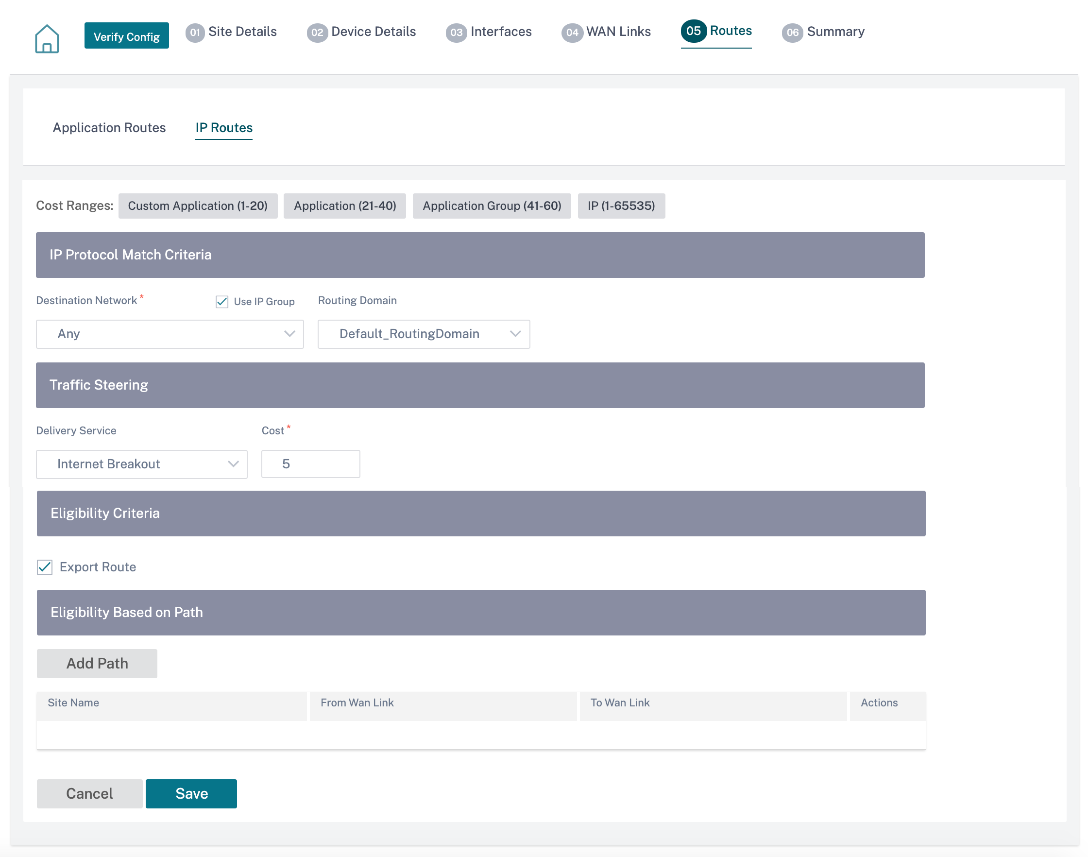
Go to IP Routes tab and click + IP Route to create the IP Route policy to steer traffic.
-
IP Protocol Match Criteria:
- Destination Network: Add the destination network that helps to forward the packets.
- Use IP Group: You can add a destination network or enable the Use IP Group check box to select any IP group from the drop-down list.
- Routing Domain: Select a routing domain from the drop-down list.
-
Traffic Steering
- Delivery Service: Choose one delivery service from the drop-down list.
- Cost: Reflects the relative priority of each route. Lower the cost, the higher the priority.
-
Eligibility Criteria:
- Export Route: If the Export Route check box is selected and if the route is a local route, then the route is eligible to be exported by default. If the route is an INTRANET/INTERNET based route, then for the export to work, WAN to WAN forwarding has to be enabled. If the Export Route check box is cleared, then the local route is not eligible to be exported to other SD-WAN and has local significance.
-
Eligibility based on Path:
- Add Path: Choose a site and WAN links, both to and from. If the added path goes down, then the IP route does not receive any traffic.
If a new IP route gets added, then the route cost must be in the 1–20 range.
Summary
This section provides a summary of the site configuration to enable a quick review before submitting the same.
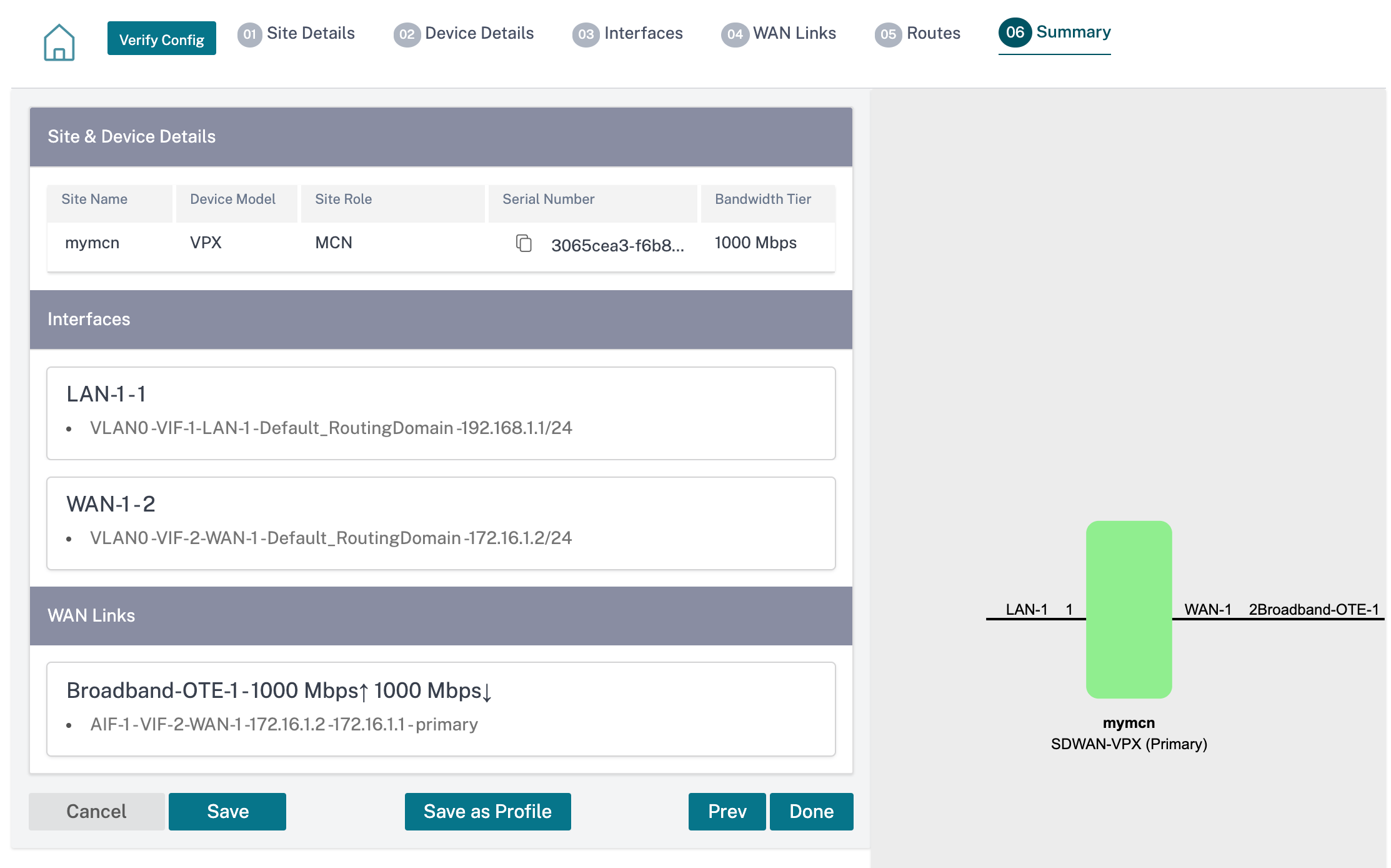
Use the Save as Template option to save the site configuration as a template for reuse across other sites. Clicking Done marks completion of site configuration, and takes you to the Network Configuration – Home page to review all the sites configured. For more information, see Network Configuration.