Deploy Citrix SD-WAN™ on AWS Outposts
AWS Outposts is a fully managed service that offers the AWS infrastructure, AWS services, APIs, and tools to virtually any data center, co-location space, or on-premises facility for a consistent hybrid cloud experience. AWS services such as compute, storage, database, and other services run locally on Outposts, and you can access the full range of AWS services available in the Region to build, manage, and scale your on-premises applications using familiar AWS services and tools.
With the addition of AWS Outposts to the AWS offering, Citrix SD-WAN customers now can use Citrix SD-WAN’s hybrid-cloud solution to easily connect AWS Outposts instances to their existing WAN infrastructure. With this integration customers will be able to manage SD-WAN connectivity from branches to the AWS cloud and Outposts using Citrix SD-WAN management tools.
- A BYOL license for Citrix SD-WAN VPX
- Minimum 40 GB storage for VPX and minimum 200 GB for VPX-L configuration
- Availability of m5 & c5 instances
- A couple of elastic IPs (for WAN interface and management interface respectively)
NOTE
You might choose not to host the management interface over a public IP.
Solution validation topology/network architecture
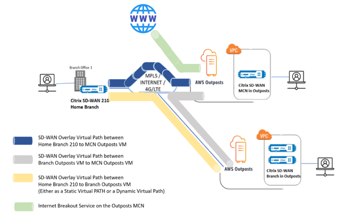
Below is the step-by-step configuration guide to provision an SD-WAN appliance in AWS Outposts.
Prerequisites
- Log into the Outposts AWS Account.
- Have access to the Citrix SD-WAN AMI from the market place of AWS Outposts.
NOte
All the snapshots of AWS Outpost console provided in the configuration guide are done with the new console launched by AWS and may not be looking exactly the same, if a legacy UI is selected.
Creation of VPC on Outposts for Citrix SD-WAN appliance (VPXL type)
- Provide a CIDR block for the AWS Outpost VPC. For this configuration we use a CIDR of 192.168.100.0/22.
- Leave all other attributes as default.
-
Provide the tag names as necessary to identify the appliance from the instance list for future.
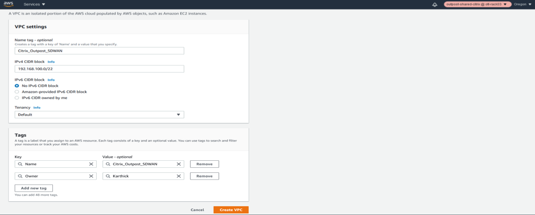
- Verify that the VPC is created and the IPv4 CIDR details are updated and a VPC ID is obtained for the resource created.
-
The status should be associated.
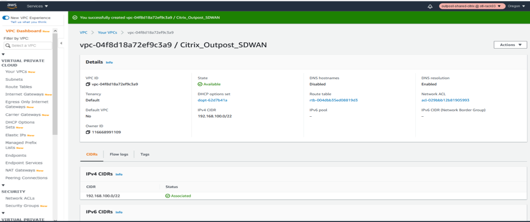
-
Once the VPC is created, the VPC list should show up the new VPC created with the CIDR details in the Your VPCs section of VPC AWS outposts service.
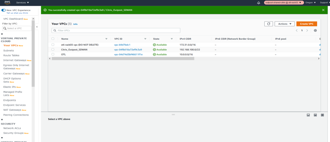
Creation of Internet Gateway and associate to VPC (Internet access for WAN and MANAGEMENT Interface of SD-WAN)
The Internet Gateway is created for the SD-WAN VPC to ensure that we have the management connectivity over the Internet and also for the WAN Link of the SD-WAN appliance to be able to form the virtual path over the Internet (Since the Azure instance hosts an Internet link)
-
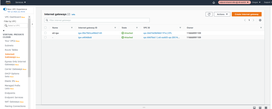
We create a single Internet Gateway instance for the VPC using “Internet Gateways” section of the VPC AWS Outpost service.
-
Click Create Internet Gateway.
Create the Internet Gateway for the VPC
-
The Internet gateway is just a resource creation and has nothing special to be configured. If needed, ensure to configure the name tag and the relevant resource tags to search for the resource among the IGW’s in the list in future.
-
Click Create Internet gateway.
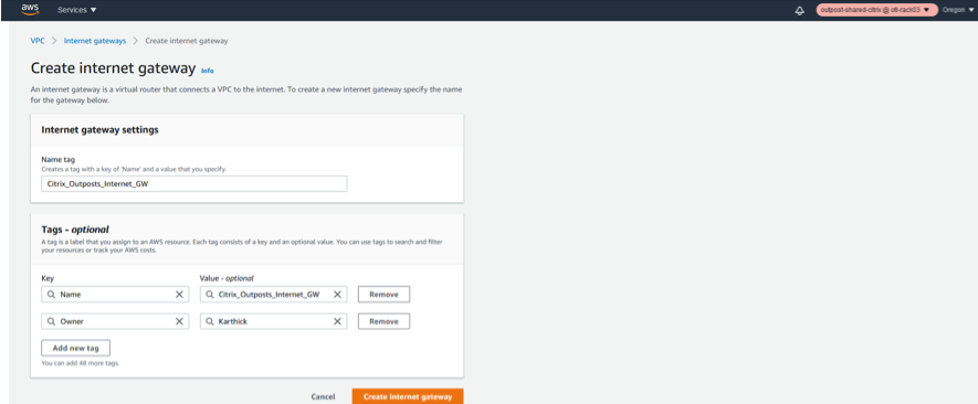
Once the Internet Gateway is created, associate the Internet gateway to a specific VPC we just created.
-
Click the IGW resource and in the actions field select Attach to VPC.
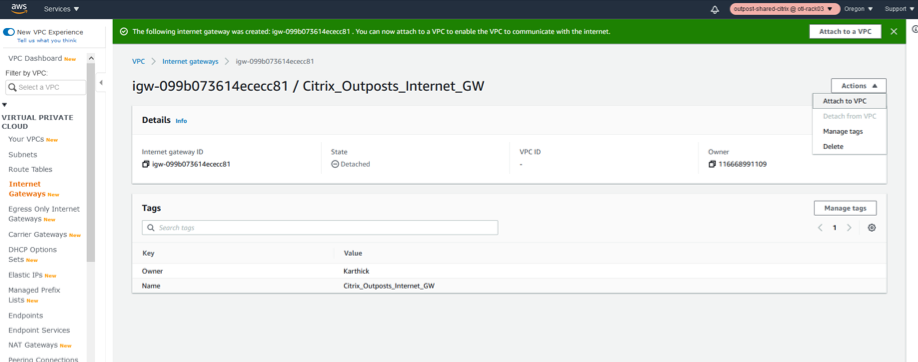
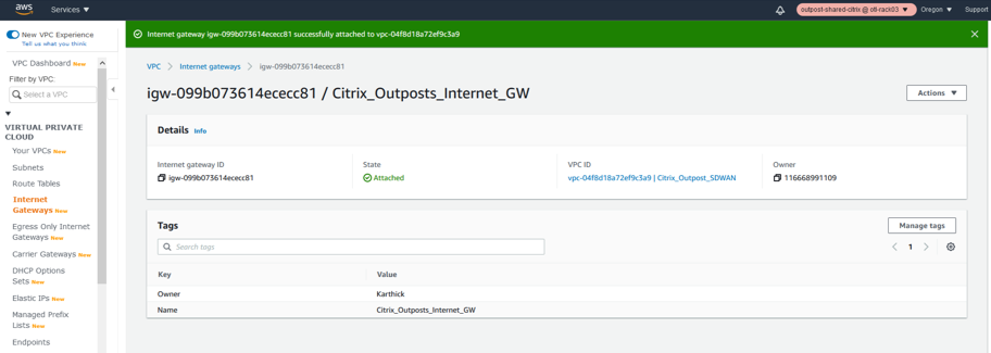
- Once the attach to VPC is clicked, select the VPC we created in step 1 which is for the SD-WAN.
- Click the Available VPC’s drop-down list and select the SD-WAN VPC created.
- Click Attach Internet Gateway.
Associate the VPC to the Internet Gateway

Creation of LAN, WAN and MGMT Subnets for Citrix SD-WAN VPXL appliance
The SD-WAN standalone appliance hosts 3 Interfaces in general.
- Management Interface
- LAN Interface
- WAN Interface
The order of association of the interfaces also are important and the first interface that is associated is the management, followed by LAN and then the WAN subnet.
Management subnet
- Click Subnets under VPC
- Click Create subnet

- In the subnet creation window, select the VPC created for SD-WAN as in step 1 and associate.
- Select any availability zone of your choice.
- Provide the management interface a subnet prefix from the VPC CIDR.
- For this configuration guide, the management interface will be configured with 192.168.102.0/24.
- Click create.


LAN subnet
- In the subnet creation window, select the VPC created for SD-WAN as in step 1 and associate.
- Select any availability zone of your choice.
- Provide the LAN interface a subnet prefix from the VPC CIDR.
- For this configuration guide, the LAN interface will be configured with 192.168.100.0/24.
-
Click Create.


WAN subnet
- In the subnet creation window, select the VPC created for SD-WAN as in step 1 and associate.
- Select any availability zone of your choice.
- Provide the LAN interface a subnet prefix from the VPC CIDR.
- For this configuration guide, the WAN interface will be configured with 192.168.101.0/24.
-
Click Create.


Define route tables for the LAN/WAN/MGMT Subnet
Route tables are helpful to signify routing for each subnet and we need to create the route tables for Management and WAN table so that the Internet access and the other related routes can be configured with the Internet Gateway configured.
Management subnet route table
- Click Route tables under VPC.
- Click create route table.
- Select the VPC created for SD-WAN in step 1.
- Click Create.
-
Create the Management route table.

-
Associate the VPC to the management Route Table.


The next step is to associate the route table to the Management subnet created.
- Select the Management route table from the list.
- Click the Actions drop-down list.
- Select Edit Subnet associations.
- Associate the Management Subnet to the route table which hosts the IP 192.168.102.0/24.
-
Edit Subnet Associations for management Route Table.


-
Add Routes for management Subnet (Default via IGW).
Next step is to add the route to the management to reach the Internet for public Access.
- Select the management route table.
- Click Edit routes.
- Provide a new DEFAULT route 0.0.0.0/0 via the IGW instance we created in step 2.
- Save Routes.


Define route tables for the WAN subnet
-
Create the Route table for WAN Interface
- Click Route tables under VPC.
- Click create route table.
- Select the VPC created for SD-WAN in step 1.
- Click create.

-
Associate the VPC to the WAN routing table.


-
Edit Subnet Associations for WAN Route Table.
The next step is to associate the route table to the WAN subnet created.
- Select the WAN route table from the list.
- Click the Actions drop-down list.
- Select Edit Subnet associations.
- Associate the WAN Subnet to the route table which hosts the IP 192.168.101.0/24.


-
Add Routes for WAN Subnet (Default via IGW).
Next step is to add the route to the WAN to reach the Internet for public Access.
- Select the WAN route table.
- Click Edit routes.
- Provide a new DEFAULT route 0.0.0.0/0 via the IGW instance we created in step 2.
- Save Routes.


Define route tables for the LAN subnet
-
Create the Route table for LAN Interface
- Click Route tables under VPC.
- Click create route table.
- Select the VPC created for SD-WAN in step 1.
- Click create.

-
Associate the LAN routing table to the VPC.


-
Edit Subnet Associations for LAN Route Table.
The next step is to associate the route table to the LAN subnet created.
- Select the WAN route table from the list.
- Click the Actions drop-down list.
- Select Edit Subnet associations.
- Associate the LAN Subnet to the route table which hosts the IP 192.168.100.0/24.


Outpost AMI Instance Provisioning/Deployment
Launch AMI Instance (Private)
-
Choose the Private AMI by uploading the shared AMI into outposts (If not published in Marketplace yet).
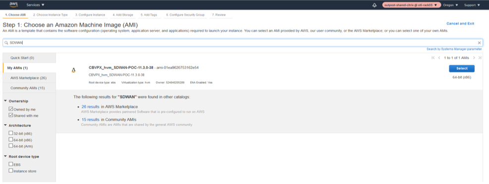
-
Select the right type of instance (VPXL – M5.2xlarge).
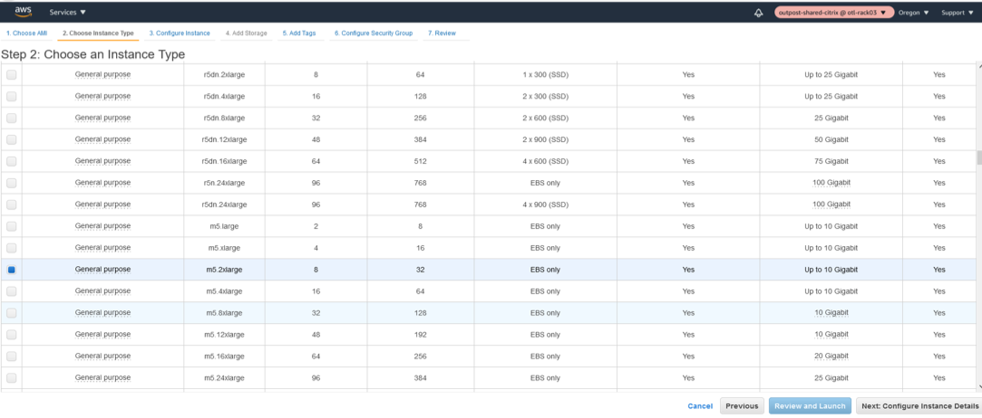
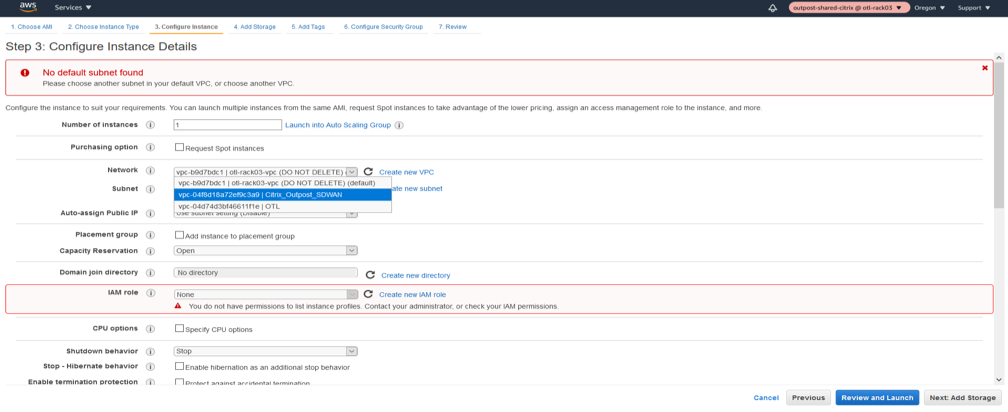
- Configure the Instance Details like the VPC network, Subnet.
- Select the VPC created for the instance in the Network.
- Select the MGMT subnet as the primary interface.
- Select Enabled for Auto assign public IP.
- Provide a custom Private IP as well for the management interface in the bottom of the instance details page.
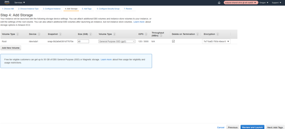
-
Select default Storage.
-
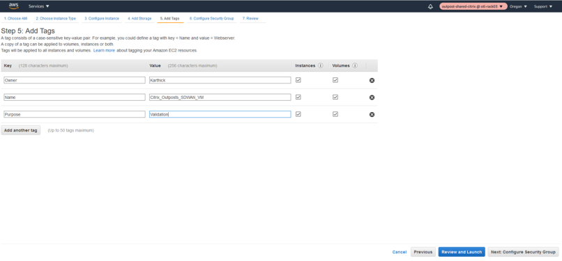
Add relevant tags for instance search/indexing later.
-
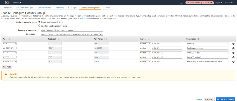
Define the relevant Security Group for the instance.
-
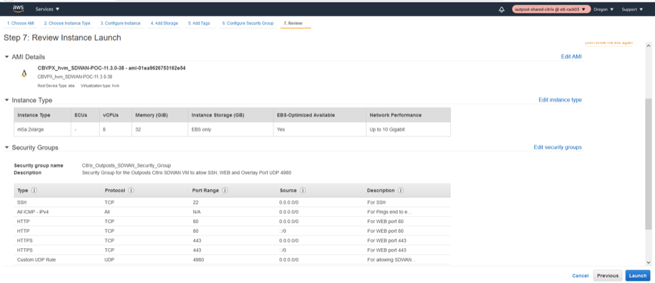
Summary of the Network Security Group of the Citrix SD-WAN Outpost Instance.
-
Download the Keypair for the instance launch via SSH for later use.

-
Initiate the LAUNCH of the instance.


-
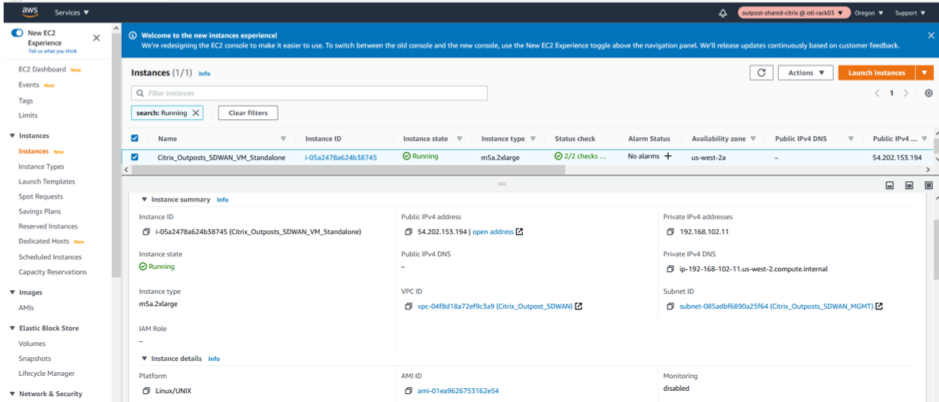
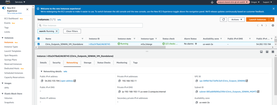
Verify the Instance status and its health check in the EX2 Dashboard post launch.

Creation of LAN/WAN Network Interfaces and Association
LAN Network Interface
-
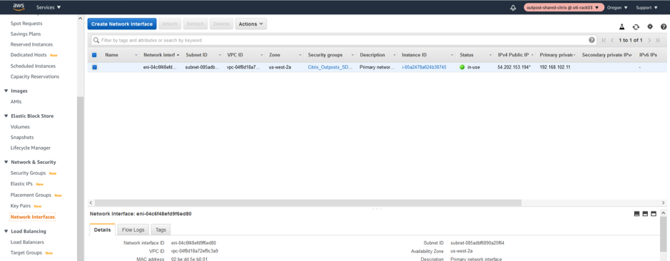
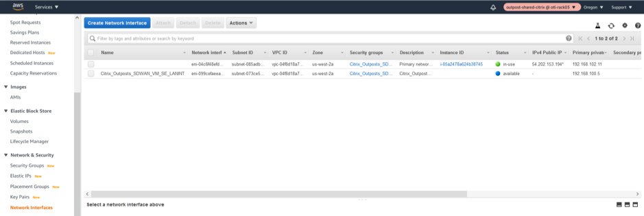
Create the LAN Network Interface.
-
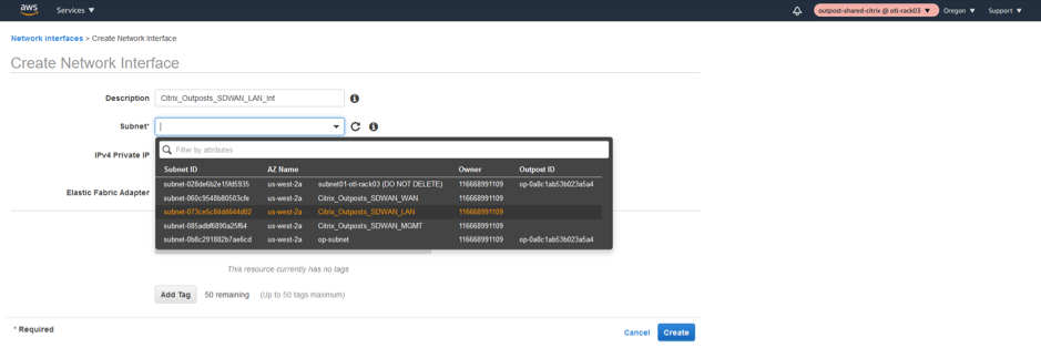
Associate the Subnet related to LAN Interface.
-
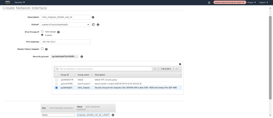
Associate a custom LAN Private IP 192.168.100.5 and associate the NSG (Network Security Group).
WAN Network Interface
-
Create the WAN Network Interface.
-
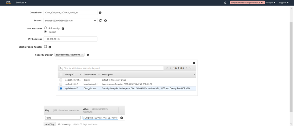
Associate the WAN Subnet to the network interface.

-
Provide a private custom WAN IP as 192.168.101.5 and associate the Network Security Group.
Change SOURCE/DEST Check on LAN/WAN/Management Interfaces
Disabling the Source/Dest. Check attribute enables the interface to handle network traffic that is not destined for the EC2 instance. As the NetScaler SD-WAN AMI acts as a go-between for network traffic, the Source/Dest. Check attribute must be disabled for proper operation.
Management Interface disable SRC/DEST check


LAN Interface disable SRC/DEST check

WAN Interface disable SRC/DEST check

Attach the LAN/WAN Network Interfaces to Outpost Citrix SD-WAN
LAN Interface Association
- Attach the LAN Network Interface to the SD-WAN.


WAN Interface Association
- Attach the WAN Network Interface to the SD-WAN.


Note
Attaching the Mgmt, LAN, and WAN in that order attaches to eth0, eth1, eth2 in the SD-WAN AMI. This aligns with the mapping of the provisioned AMI and ensures that interfaces are not reassigned incorrectly in the event of AMI reboot.
Create and Associate ELASTIC IPs to MGMT and WAN Interfaces of Outpost Citrix SD-WAN
Management IP Elastic IP
-
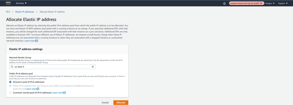
Allocate a new ELASTIC IP for MGMT Interface.


-
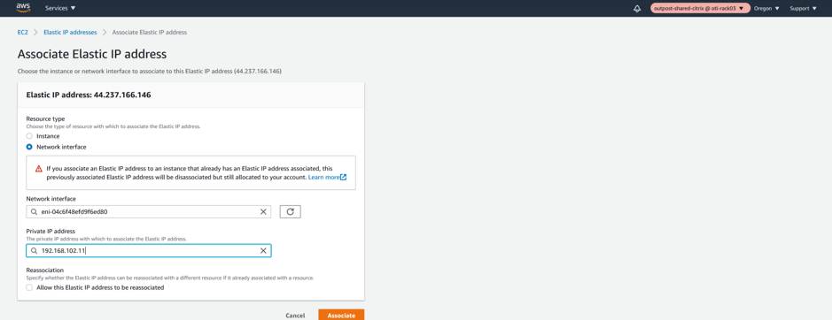
Associate the newly created ELASTIC IP to Management Interface.
The Management Elastic IP is needed for SSH/UI browsing over 80/443 of the Outpost based Citrix SD-WAN appliance. This makes management simpler.
We will be specifically linking the elastic IP to the Management Network Interface and further specifically to th private IP associated with the management subnet which is “192.168.102.11”.
- Select Network Interface
- Select the Management network interface
- Assign a private IP Address “192.168.102.11”
- Associate

WAN Interface Elastic IP
-
Allocate a new ELASTIC IP for WAN Interface
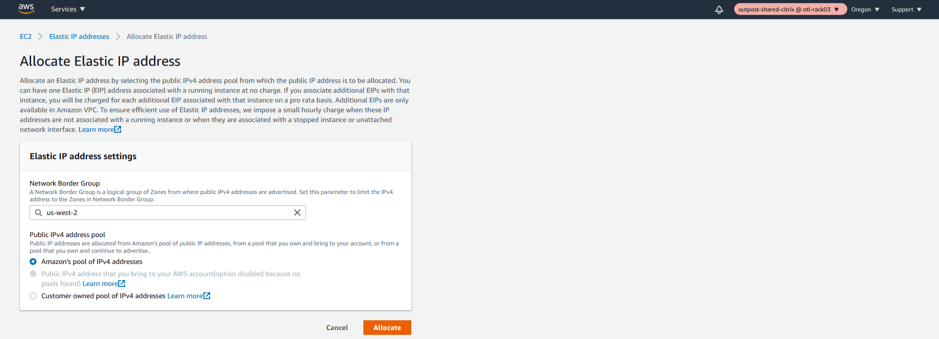

-
Associate the newly created ELASTIC IP to WAN Interface.
The WAN Elastic IP is needed for enabling the overlay communication between different sites to the Outpost based Citrix SD-WAN appliance and have the IP connectivity to the external world. This would be the Public IP of the WAN Link that we will provide for an MCN or a Branch. This IP is essentially to be known by all the remote appliances/peers to help have an overlay control/data channel establishment. We will be specifically linking the elastic IP to the WAN Network Interface and further specifically to the private IP associated with the WAN subnet which is “192.168.102.11”.
- Select Network Interface
- Select the WAN network interface
- Assign a private IP Address “192.168.101.5”
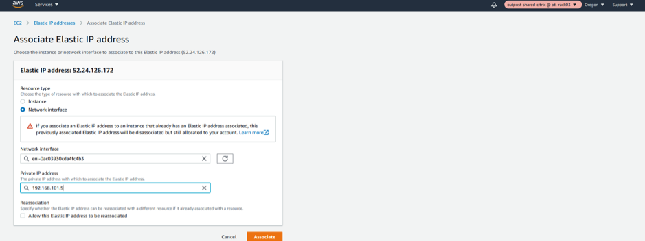

Outpost VPXL SD-WAN VM as an MCN
Access/Configure the Outpost Citrix SD-WAN as an MCN
-
Access MGMT Interface IP.
Note down the elastic IP of the Management interface and type in
https://<elastic_ip_mgmt_interface>to access the SD-WAN UI.
-
Authenticate with admin credentials.
User name is admin and password is the INSTANCE ID (Highlighted below)

-
Make the role of the Outpost Citrix SD-WAN VM as an MCN (Master Control Node)
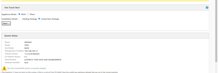

-
Add a new site for the MCN (Outpost SD-WAN).
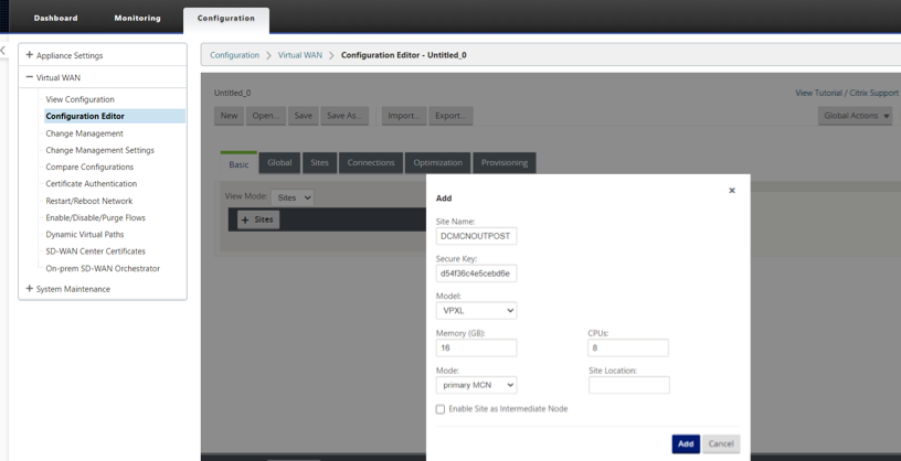
-
Configure the Outpost VM (MCN) Network Interface Groups for LAN and WAN.
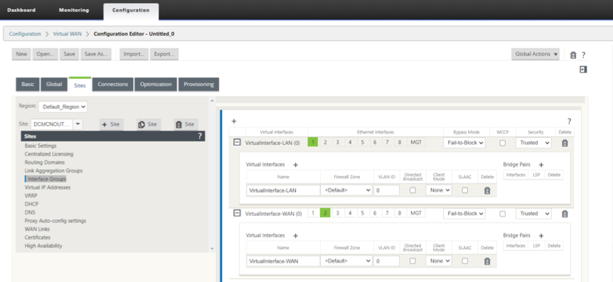
-
Configure the Outpost VM (MCN) Virtual IP Addresses (VIPs) for LAN and WAN.
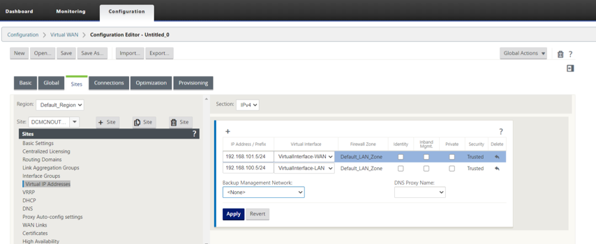
-
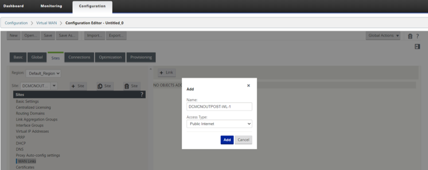
Configure the Outpost VM (MCN) WAN Link.
-
DOWNLOAD/UPLOAD capacity definitions on the WAN link.
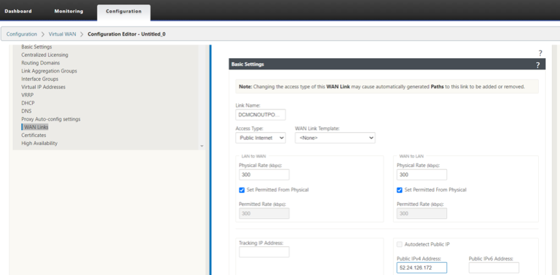
-
Configure the Access Interface and the Gateway IP of the WAN Link.
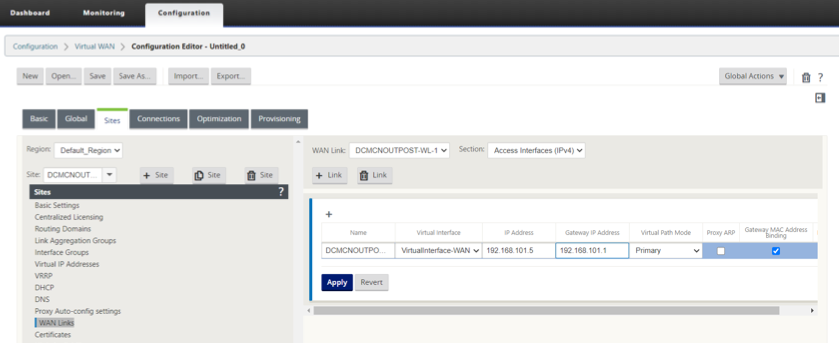
-
Citrix SD-WAN 210 as a HOME USER BRANCH SD-WAN
Configure the 210 Citrix SD-WAN as a BRANCH
-
Add a 210 site as a Branch in Client mode.
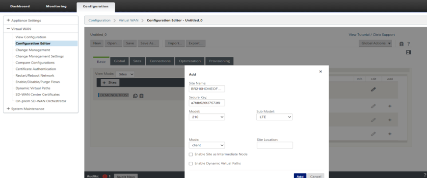
-
Configure the 210 HOME OFFICE Branch Network Interface Groups for LAN and WAN.
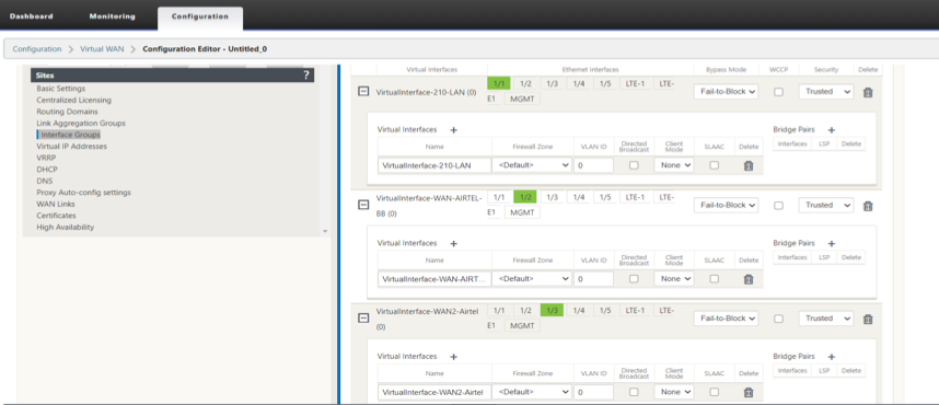
-
Configure the 210 HOME OFFICE Branch Virtual IP Addresses (VIPs) for LAN and WAN.
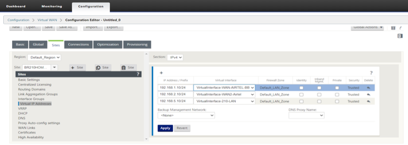
-
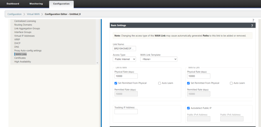
Configure the 210 HOME OFFICE Branch WAN Link.
-
DOWNLOAD/UPLOAD capacity definitions on the WAN link.
-
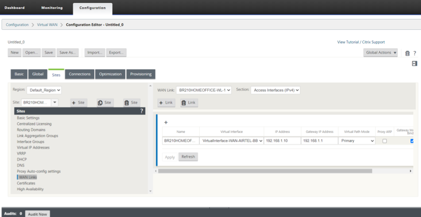
Configure the Access Interface and the Gateway IP of the WAN Link.
-
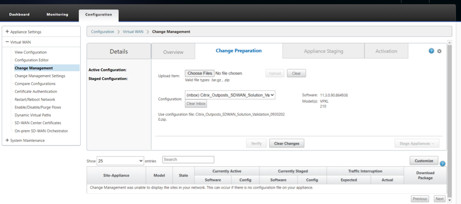
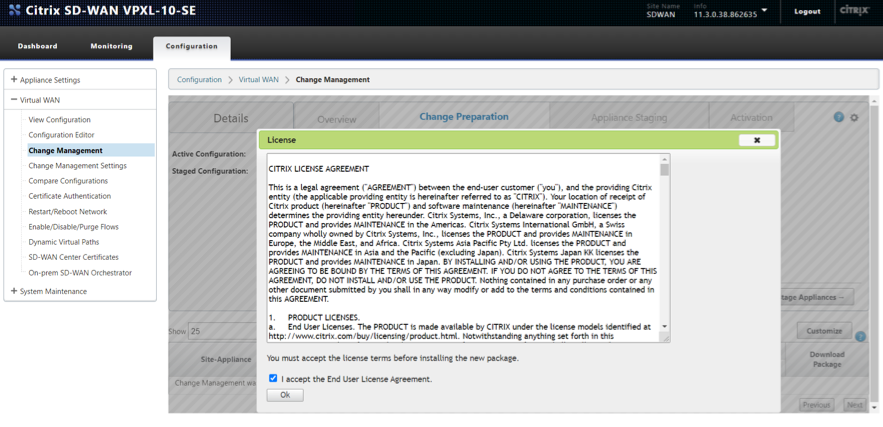
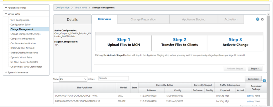
Perform Change Management and Stage the configuration to the appliances
Activate the Configuration
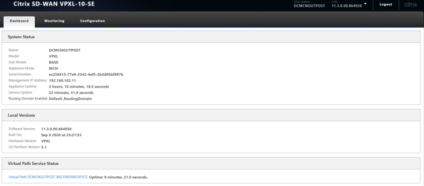
Verify the Virtual PATH creation
On the Outpost MCN VM
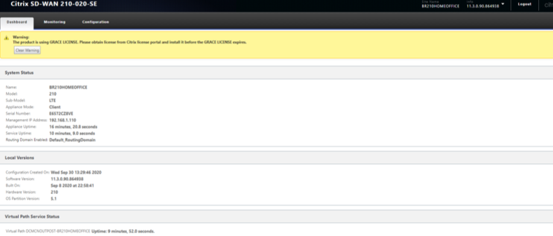
On the 210 HOME Branch
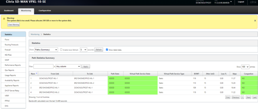
Validate Traffic over Virtual PATH between Outpost VM and 210 Branch.
- Step 1 – Initiate Ping between the 210 Branch and the Outposts MCN
- Step 2 – Check Flows on both 210 and MCN VM on Upload/Download direction and verify the SIP, DIP, IP Protocol and the Service used for processing traffic
- Step 3 – Check firewall connection on the Outpost MCN and the 210 for the ICMP traffic between the 2 sites
-
Verify that Ping traffic initiated between the 210 Branch and the Outposts MCN is processed via Virtual Path
-
Flows should indicate flows via right service type as Virtual Path
- Check Flows on Outpost MCN – SIP, DIP, IP Protocol should match including Service as Virtual Path
- Check the paths in the flow for best path used – Should be one of the best paths in the list of paths available
-
Check flows on the 210 Branch - SIP, DIP, IP Protocol should match including Service as Virtual Path
- Check the paths in the flow for best path used – Should be one of the best paths in the list of paths available
-
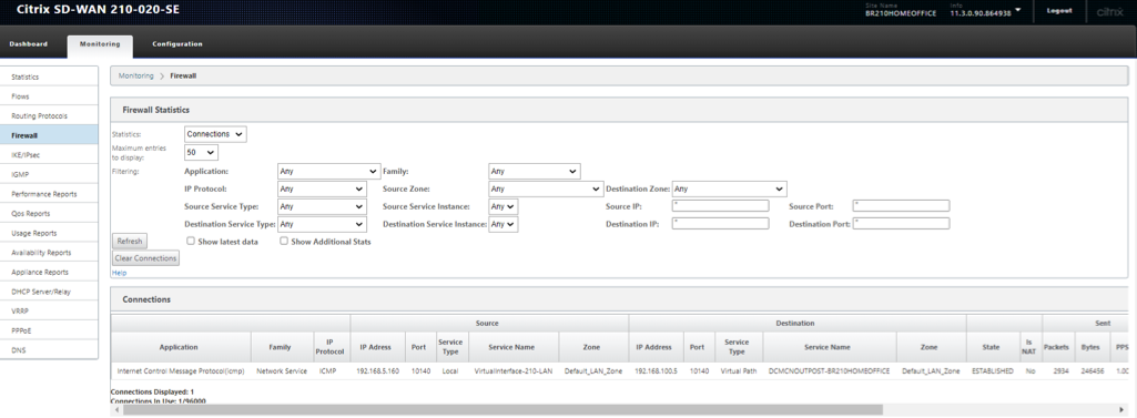
Check Firewall to check the connection
- Check Firewall on the Outpost MCN should have the connection information with the Application as ICMP for response. Should have SIP-SPORT (MCN), DIP-DPORT (210) including Source Service and Dest service as Local and Virtual Path respectively
- Source
- Check Firewall on the 210 Branch should have the connection information with the Application as ICMP for request. Should have SIP-SPORT (210), DIP-DPORT (MCN) including Source Service and Dest service as Local and Virtual Path respectively
-
Initiate PING from the end laptop to 192.168.100.5 (LAN side VIP of the Outposts SD-WAN)
- Command – ping 192.168.100.5
- Source Ip address of initiating laptop – 192.168.5.160
- This traffic is intended to traverse the Virtual path due to the routing table installed on the branch with the 192.168.100.0/24 installed as a prefix reachable over VP
Initiate PING from the end laptop to 192.168.100.5 (LAN side VIP of the SD-WAN)
Verify Flows that the LAN to WAN and WAN to LAN direction entries are seen in both the MCN (Outpost VM) and the 210 Branch
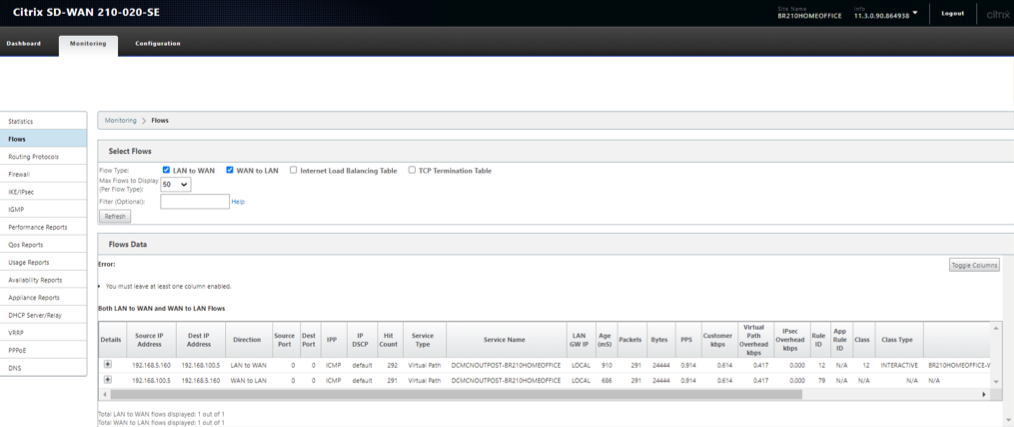
Verify FLOWS on the 210 Home Branch
On the Home Branch
LAN to WAN (From Branch towards MCN)
- Source IP – 192.168.5.160
- Dest IP – 192.168.100.5
- Proto/IPP – ICMP
WAN to LAN (From MCN towards Branch)
- Dest IP – 192.168.5.160
- Source IP – 192.168.100.5
- Proto/IPP – ICMP
-
Verify that the service used is Virtual Path and the service name is that if between the MCN (Outpost VM) to the Branch 210
-
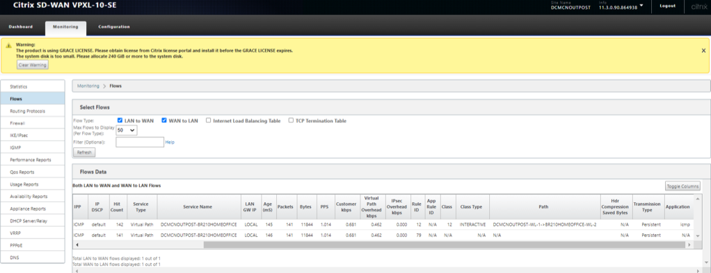
Also check the path will display the current best path that is taking the ICMP traffic through the Virtual Path (Which is WL1 on the 210 to the only existing link at the MCN side)
Note
Check the current path in the “Path” Column in the below snapshot.
Verify on the MCN (Outposts VM)
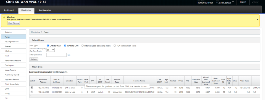
On the MCN Outpost VM side
WAN to LAN (From Branch towards MCN)
- Source IP – 192.168.5.160
- Dest IP – 192.168.100.5
- Proto/IPP – ICMP
LAN to WAN (From MCN towards Branch)
- Dest IP – 192.168.5.160
- Source IP – 192.168.100.5
- Proto/IPP – ICMP
-
Verify that the service used is Virtual Path and the service name is that if between the MCN (Outpost VM) to the Branch 210
-
Also check the path will display the current best path that is taking the ICMP traffic through the Virtual Path (Which is WL1 on the 210 to the only existing link at the MCN side)
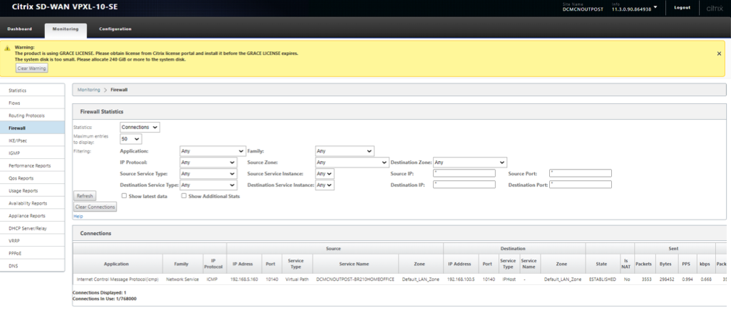
Verify Firewall details on the MCN (Outposts VM)
Below details are validated for the flow at the MCN (Outposts VM)
- Application – ICMP
- Source Service – Virtual PATH (Traffic came via VP from the Branch side)
- Destination Service – IPHOST (Because we are pinging to the IP of the SD-WAN and is intended to the device)
- State - Established
For information on support policies, see support and services
Verify Firewall details on 210 Home Branch
Below details are validated for the flow at the 210 Branch side.
- Application – ICMP
- Source Service – Local (Initiated from a host behind the 210 Branch)
- Destination Service – Virtual Path (Because we are pinging to the IP of the SD-WAN and is intended to the device and is carried via Virtual Path)
- State - Established
For information on support policies see support and services
In this article
- Solution validation topology/network architecture
- Creation of VPC on Outposts for Citrix SD-WAN appliance (VPXL type)
- Creation of Internet Gateway and associate to VPC (Internet access for WAN and MANAGEMENT Interface of SD-WAN)
- Creation of LAN, WAN and MGMT Subnets for Citrix SD-WAN VPXL appliance
- Define route tables for the LAN/WAN/MGMT Subnet
- Define route tables for the WAN subnet
- Define route tables for the LAN subnet
- Outpost AMI Instance Provisioning/Deployment
- Creation of LAN/WAN Network Interfaces and Association
- Change SOURCE/DEST Check on LAN/WAN/Management Interfaces
- Attach the LAN/WAN Network Interfaces to Outpost Citrix SD-WAN
- Create and Associate ELASTIC IPs to MGMT and WAN Interfaces of Outpost Citrix SD-WAN
- Outpost VPXL SD-WAN VM as an MCN
- Citrix SD-WAN 210 as a HOME USER BRANCH SD-WAN
- Perform Change Management and Stage the configuration to the appliances
- Activate the Configuration
- Verify the Virtual PATH creation
- Initiate PING from the end laptop to 192.168.100.5 (LAN side VIP of the Outposts SD-WAN)
- Initiate PING from the end laptop to 192.168.100.5 (LAN side VIP of the SD-WAN)
- Verify FLOWS on the 210 Home Branch
- Verify on the MCN (Outposts VM)
- Verify Firewall details on 210 Home Branch