-
-
-
-
-
XenServer 6.5 Upgrade for SD-WAN Standard Edition Appliances
-
SD-WAN Standard Edition Virtual Appliance (VPX) in Hypervisor on HyperV 2012 R2 and 2016
-
Install SD-WAN SE Virtual Appliances (VPX) in Linux-KVM Platform
-
Deploy Citrix SD-WAN Standard Edition Instance on Azure - Release Version 10.2 and above
-
SD-WAN Standard Edition Virtual Appliance (VPX) High Availability support for AWS
-
Deploy a Citrix SD-WAN VPX instance on a Citrix® ADC SDX appliance
-
This content has been machine translated dynamically.
Dieser Inhalt ist eine maschinelle Übersetzung, die dynamisch erstellt wurde. (Haftungsausschluss)
Cet article a été traduit automatiquement de manière dynamique. (Clause de non responsabilité)
Este artículo lo ha traducido una máquina de forma dinámica. (Aviso legal)
此内容已经过机器动态翻译。 放弃
このコンテンツは動的に機械翻訳されています。免責事項
이 콘텐츠는 동적으로 기계 번역되었습니다. 책임 부인
Este texto foi traduzido automaticamente. (Aviso legal)
Questo contenuto è stato tradotto dinamicamente con traduzione automatica.(Esclusione di responsabilità))
This article has been machine translated.
Dieser Artikel wurde maschinell übersetzt. (Haftungsausschluss)
Ce article a été traduit automatiquement. (Clause de non responsabilité)
Este artículo ha sido traducido automáticamente. (Aviso legal)
この記事は機械翻訳されています.免責事項
이 기사는 기계 번역되었습니다.책임 부인
Este artigo foi traduzido automaticamente.(Aviso legal)
这篇文章已经过机器翻译.放弃
Questo articolo è stato tradotto automaticamente.(Esclusione di responsabilità))
Translation failed!
Connecting the Cables
When the appliance is securely mounted on the rack, determine which ports you should use. You are then ready to connect the cables. Ethernet cables and the optional console cable are connected first. Connect the power cable last.
Warning: Before installing or repairing the appliance, remove all jewelry and other metal objects that might come in contact with power sources or wires. When you touch both a live power source or wire and ground, any metal objects can heat up rapidly and cause burns, set clothing on fire, or fuse the metal object to an exposed terminal.
Ports
A typical installation using a single accelerated bridge uses four Ethernet ports (the Primary port and apA) and six IP addresses (four on the Primary port’s subnet and two on apA’s subnet).
The appliance has two motherboard ports and two (SD-WAN 400/800 and SD-WAN 1000/2000) or three (SD-WAN 3000) accelerated bridges.
- The motherboard ports are labeled as MGMT (management) and AUX1 (auxiliary) ports in SD-WAN1000 appliance with Windows Server and PRI (primary) and AUX (auxiliary) in SD-WAN 2000 appliance with Windows Server.
- You use MGMT port of the SD-WAN 1000 appliance with Windows Server and PRI port of the SD-WAN 2000 appliance with Windows Server for initial configuration.
- The SD-WAN 400/800/1000 and 2000 appliances each have two pairs of accelerated bridge ports. The 3000 appliance has three pairs of accelerated-bridge ports. On the appliance, ports 1/1 and 1/2 are the accelerated pair A (apA) bridge ports, ports 1/3 and 1/4 are the apB ports, and ports 1/5 and 1/6 are the apC bridge ports.
- Accelerated bridge ports are apA and apB are available on the back panel of SD-WAN 1000 appliance with Windows Server and the front panel of SD-WAN 2000 appliance with Windows Server. On SD-WAN 1000WS appliance with Windows Server, these ports are labeled as LAN1 and WAN1, and LAN2 and WAN2, respectively. However, on SD-WAN 2000WS appliance with Windows Server, these ports are labeled as 1/1 and 1/2, and 1/3 and 1/4, respectively.
Connect the ethernet cables
Ethernet cables connect your appliance to the network. The type of cable you need depends on the type of port used to connect to the network. Use a category 5e or category 6 Ethernet cable with a standard RJ-45 connector on a 10/100/1000BASE-T port.
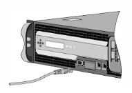
To connect an Ethernet cable to a 10/100/1000BASE-T port:
- Insert the RJ-45 connector on one end of your Ethernet cable into an appropriate port of the appliance.
- Insert the RJ-45 connector on the other end into the target device, such as a router or switch.
- Verify that the LED glows amber when the connection is established.
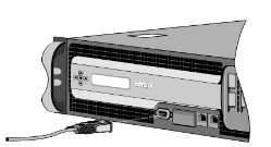
Connecting the console cable
You can use the console cable to connect your appliance to a computer or terminal, from which you can configure the appliance. Before connecting the console cable, configure the computer or terminal to support VT100 terminal emulation, 9600 baud, 8 data bits, 1 stop bit, parity, and flow control set to NONE. Then connect one end of the console cable to the RS232 serial port on the appliance and the other end to the computer or terminal.
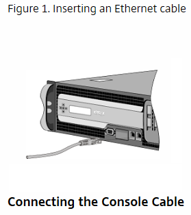
To connect the console cable to a computer or terminal:
-
Insert the DB-9 connector at the end of the cable into the console port. On SD-WAN 1000 appliance with Windows Server, the port is located on the back panel. On SD-WAN 2000 appliance with Windows Server, the port is located on the front panel.
Note: To use a cable with an RJ-45 converter, insert the optional converter provided into the console port and attach the cable to it.
-
Insert the RJ-45 connector at the other end of the cable into the serial port of the computer or terminal.
Connect the power cable
An SD-WAN appliance has one power supply, unless you have installed a second. A separate ground cable is not required, because the three-prong plug provides grounding. Provide power to the appliance by installing the power cord. Connect the other end of the power cable to a standard 110V/220V power outlet.
- Connect one end of the power cable to the power outlet on the back panel of the appliance, next to the power supply.
- Connect the other end of the power cable to a standard 110V/220V power outlet.
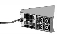
The SD-WAN 4000/5000 appliance has two power supplies, with one serving as a backup. A separate ground cable is not required, because the three-prong plug provides grounding. Power up the appliance by installing one or both power cords.
Note
The appliance emits a high-pitched alert if one power supply fails or if you connect only one power cable to the appliance. To silence the alarm, you can press the small red button on the back panel of the appliance.
Share
Share
This Preview product documentation is Cloud Software Group Confidential.
You agree to hold this documentation confidential pursuant to the terms of your Cloud Software Group Beta/Tech Preview Agreement.
The development, release and timing of any features or functionality described in the Preview documentation remains at our sole discretion and are subject to change without notice or consultation.
The documentation is for informational purposes only and is not a commitment, promise or legal obligation to deliver any material, code or functionality and should not be relied upon in making Cloud Software Group product purchase decisions.
If you do not agree, select I DO NOT AGREE to exit.