-
Getting Started with NetScaler
-
How a NetScaler Communicates with Clients and Servers
-
Solutions for Telecom Service Providers
-
Load Balance Control-Plane Traffic that is based on Diameter, SIP, and SMPP Protocols
-
Provide Subscriber Load Distribution Using GSLB Across Core-Networks of a Telecom Service Provider
-
Authentication, authorization, and auditing application traffic
-
Basic components of authentication, authorization, and auditing configuration
-
Web Application Firewall protection for VPN virtual servers and authentication virtual servers
-
On-premises NetScaler Gateway as an identity provider to Citrix Cloud™
-
Authentication, authorization, and auditing configuration for commonly used protocols
-
Troubleshoot authentication and authorization related issues
-
-
-
-
-
-
Persistence and persistent connections
-
Advanced load balancing settings
-
Gradually stepping up the load on a new service with virtual server–level slow start
-
Protect applications on protected servers against traffic surges
-
Retrieve location details from user IP address using geolocation database
-
Use source IP address of the client when connecting to the server
-
Use client source IP address for backend communication in a v4-v6 load balancing configuration
-
Set a limit on number of requests per connection to the server
-
Configure automatic state transition based on percentage health of bound services
-
-
Use case 2: Configure rule based persistence based on a name-value pair in a TCP byte stream
-
Use case 3: Configure load balancing in direct server return mode
-
Use case 6: Configure load balancing in DSR mode for IPv6 networks by using the TOS field
-
Use case 7: Configure load balancing in DSR mode by using IP Over IP
-
Use case 10: Load balancing of intrusion detection system servers
-
Use case 11: Isolating network traffic using listen policies
-
Use case 12: Configure Citrix Virtual Desktops for load balancing
-
Use case 13: Configure Citrix Virtual Apps and Desktops for load balancing
-
Use case 14: ShareFile wizard for load balancing Citrix ShareFile
-
Use case 15: Configure layer 4 load balancing on the NetScaler appliance
-
-
-
-
Authentication and authorization for System Users
-
-
Configuring a CloudBridge Connector Tunnel between two Datacenters
-
Configuring CloudBridge Connector between Datacenter and AWS Cloud
-
Configuring a CloudBridge Connector Tunnel Between a Datacenter and Azure Cloud
-
Configuring CloudBridge Connector Tunnel between Datacenter and SoftLayer Enterprise Cloud
-
Configuring a CloudBridge Connector Tunnel Between a NetScaler Appliance and Cisco IOS Device
-
CloudBridge Connector Tunnel Diagnostics and Troubleshooting
This content has been machine translated dynamically.
Dieser Inhalt ist eine maschinelle Übersetzung, die dynamisch erstellt wurde. (Haftungsausschluss)
Cet article a été traduit automatiquement de manière dynamique. (Clause de non responsabilité)
Este artículo lo ha traducido una máquina de forma dinámica. (Aviso legal)
此内容已经过机器动态翻译。 放弃
このコンテンツは動的に機械翻訳されています。免責事項
이 콘텐츠는 동적으로 기계 번역되었습니다. 책임 부인
Este texto foi traduzido automaticamente. (Aviso legal)
Questo contenuto è stato tradotto dinamicamente con traduzione automatica.(Esclusione di responsabilità))
This article has been machine translated.
Dieser Artikel wurde maschinell übersetzt. (Haftungsausschluss)
Ce article a été traduit automatiquement. (Clause de non responsabilité)
Este artículo ha sido traducido automáticamente. (Aviso legal)
この記事は機械翻訳されています.免責事項
이 기사는 기계 번역되었습니다.책임 부인
Este artigo foi traduzido automaticamente.(Aviso legal)
这篇文章已经过机器翻译.放弃
Questo articolo è stato tradotto automaticamente.(Esclusione di responsabilità))
Translation failed!
How a NetScaler appliance communicates with clients and servers
A NetScaler appliance is usually deployed in front of a server farm and functions as a transparent TCP proxy between clients and servers, without requiring any client-side configuration. This basic mode of operation is called Request Switching technology and is the core of NetScaler functionality. Request Switching enables an appliance to multiplex and offload the TCP connections, maintain persistent connections, and manage traffic at the request (application layer) level. This is possible because the appliance can separate the HTTP request from the TCP connection on which the request is delivered.
Depending on the configuration, an appliance might process the traffic before forwarding the request to a server. For example, if the client attempts to access a secure application on the server, the appliance might perform the necessary SSL processing before sending traffic to the server.
To facilitate efficient and secure access to server resources, an appliance uses a set of IP addresses collectively known as NetScaler-owned IP addresses. To manage your network traffic, you assign NetScaler-owned IP addresses to virtual entities that become the building blocks of your configuration. For example, to configure load balancing, you create virtual servers to receive client requests and distribute them to services, which are entities representing the applications on your servers.
Understanding NetScaler-owned IP addresses
To function as a proxy, a NetScaler appliance uses a variety of IP addresses. The key NetScaler-owned IP addresses are:
-
NetScaler IP (NSIP) address
The NSIP address is the IP address for management and general system access to the appliance itself, and for communication between appliances in a high availability configuration.
-
Virtual server IP (VIP) address
A VIP address is the IP address associated with a virtual server. It is the public IP address to which clients connect. An appliance managing a wide range of traffic may have many VIPs configured.
-
Subnet IP (SNIP) address
A SNIP address is used in connection management and server monitoring. You can specify multiple SNIP addresses for each subnet. SNIP addresses can be bound to a VLAN.
-
IP Set
An IP set is a set of IP addresses, which are configured on the appliance as SNIP . An IP set is identified with a meaningful name that helps in identifying the usage of the IP addresses contained in it.
-
Net Profile
A net profile (or network profile) contains an IP address or an IP set. A net profile can be bound to load balancing or content switching virtual servers, services, service groups, or monitors. During communication with physical servers or peers, the appliance uses the addresses specified in the profile as source IP addresses.
How Traffic flows are managed
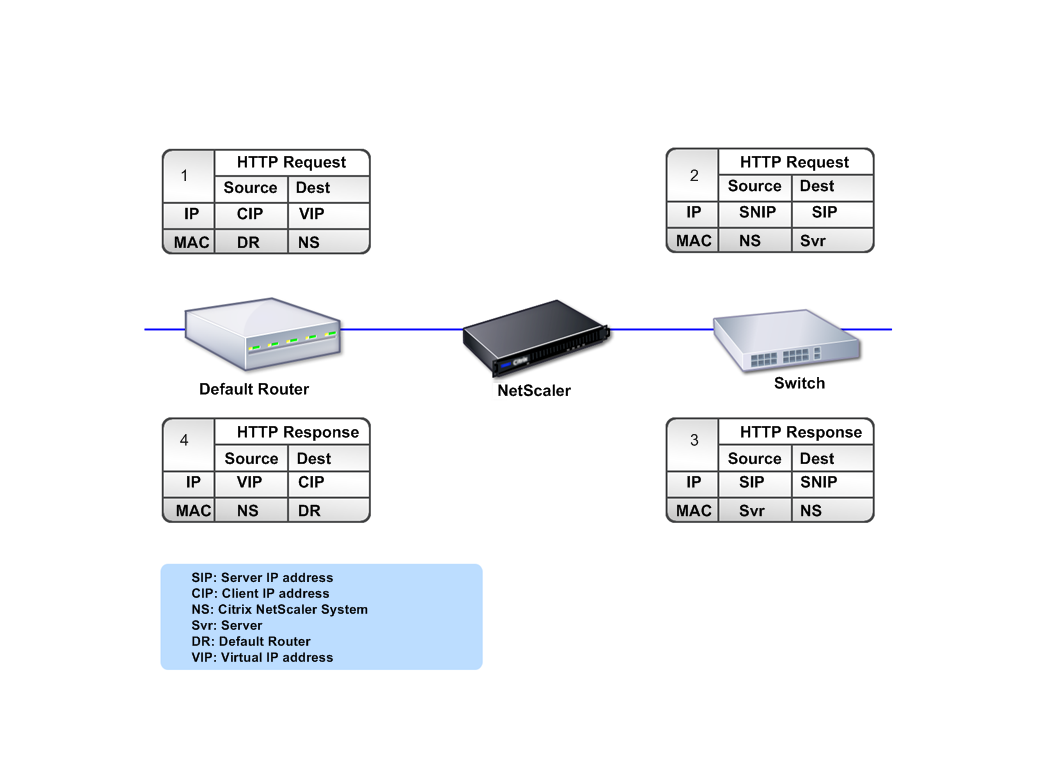
Because a NetScaler appliance functions as a TCP proxy, it translates IP addresses before sending packets to a server. When you configure a virtual server, clients connect to a VIP address on the NetScaler appliance instead of directly connecting to a server. As determined by the settings on the virtual server, the appliance selects an appropriate server and sends the client’s request to that server. By default, the appliance uses a SNIP address to establish connections with the server, as shown in the following figure.
Figure 1. Virtual Server Based Connections

In the absence of a virtual server, when an appliance receives a request, it transparently forwards the request to the server. This is called the transparent mode of operation. When operating in transparent mode, an appliance translates the source IP addresses of incoming client requests to the SNIP address but does not change the destination IP address. For this mode to work, L2 or L3 mode has to be configured appropriately.
For cases in which the servers need the actual client IP address, the appliance can be configured to modify the HTTP header by inserting the client IP address as an additional field, or configured to use the client IP address instead of a SNIP address for connections to the servers.
Traffic management building blocks
The configuration of a NetScaler appliance is typically built up with a series of virtual entities that serve as building blocks for traffic management. The building block approach helps separate traffic flows. Virtual entities are abstractions, typically representing IP addresses, ports, and protocol handlers for processing traffic. Clients access applications and resources through these virtual entities. The most commonly used entities are virtual servers and services. Virtual servers represent groups of servers in a server farm or remote network, and services represent specific applications on each server.
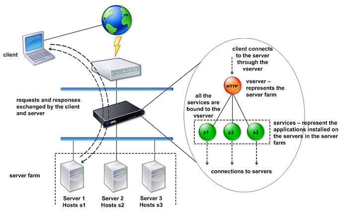
Most features and traffic settings are enabled through virtual entities. For example, you can configure an appliance to compress all server responses to a client that is connected to the server farm through a particular virtual server. To configure the appliance for a particular environment, you need to identify the appropriate features and then choose the right mix of virtual entities to deliver them. Most features are delivered through a cascade of virtual entities that are bound to each other. In this case, the virtual entities are like blocks being assembled into the final structure of a delivered application. You can add, remove, modify, bind, enable, and disable the virtual entities to configure the features. The following figure shows the concepts covered in this section.
Figure 2. How traffic management building blocks work

A simple load balancing configuration
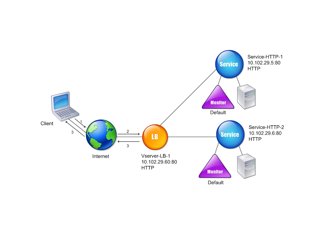
In the example shown in the following figure, the NetScaler appliance is configured to function as a load balancer. For this configuration, you need to configure virtual entities specific to load balancing and bind them in a specific order. As a load balancer, an appliance distributes client requests across several servers and thus optimizes the utilization of resources.
The basic building blocks of a typical load balancing configuration are services and load balancing virtual servers. The services represent the applications on the servers. The virtual servers abstract the servers by providing a single IP address to which the clients connect. To ensure that client requests are sent to a server, you need to bind each service to a virtual server. That is, you must create services for every server and bind the services to a virtual server. Clients use the VIP address to connect to a NetScaler appliance. When the appliance receives client requests sent to the VIP address, it sends them to a server determined by the load balancing algorithm. Load balancing uses a virtual entity called a monitor to track whether a specific configured service (server plus application) is available to receive requests.
Figure 3. Load balancing virtual server, services, and monitors

In addition to configuring the load balancing algorithm, you can configure several parameters that affect the behavior and performance of the load balancing configuration. For example, you can configure the virtual server to maintain persistence based on source IP address. The appliance then directs all requests from any specific IP address to the same server.
Understanding virtual servers
A virtual server is a named NetScaler entity that external clients can use to access applications hosted on the servers. It is represented by an alphanumeric name, virtual IP (VIP) address, port, and protocol. The name of the virtual server is of only local significance and is designed to make the virtual server easier to identify. When a client attempts to access applications on a server, it sends a request to the VIP instead of the IP address of the physical server. When the appliance receives a request at the VIP address, it terminates the connection at the virtual server and uses its own connection with the server on behalf of the client. The port and protocol settings of the virtual server determine the applications that the virtual server represents. For example, a web server can be represented by a virtual server and a service whose port and protocol are set to 80 and HTTP, respectively. Multiple virtual servers can use the same VIP address but different protocols and ports.
Virtual servers are points for delivering features. Most features, like compression, caching, and SSL offload, are normally enabled on a virtual server. When the appliance receives a request at a VIP address, it chooses the appropriate virtual server by the port on which the request was received and its protocol. The appliance then processes the request as appropriate for the features configured on the virtual server.
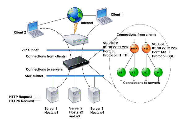
In most cases, virtual servers work in tandem with services. You can bind multiple services to a virtual server. These services represent the applications running on physical servers in a server farm. After the appliance processes requests received at a VIP address, it forwards them to the servers as determined by the load balancing algorithm configured on the virtual server. The following figure illustrates these concepts.
Figure 4. Multiple Virtual Servers with a Single VIP Address

The preceding figure shows a configuration consisting of two virtual servers with a common VIP address but different ports and protocols. Each of the virtual servers has two services bound to it. The services s1 and s2 are bound to VS_HTTP and represent the HTTP applications on Server 1 and Server 2. The services s3 and s4 are bound to VS_SSL and represent the SSL applications on Server 2 and Server 3 (Server 2 provides both HTTP and SSL applications). When the appliance receives an HTTP request at the VIP address, it processes the request as specified by the settings of VS_HTTP and sends it to either Server 1 or Server 2. Similarly, when the appliance receives an HTTPS request at the VIP address, it processes it as specified by the settings of VS_SSL and it sends it to either Server 2 or Server 3.
Virtual servers are not always represented by specific IP addresses, port numbers, or protocols. They can be represented by wildcards, in which case they are known as wildcard virtual servers. For example, when you configure a virtual server with a wildcard instead of a VIP, but with a specific port number, the appliance intercepts and processes all traffic conforming to that protocol and destined for the predefined port. For virtual servers with wildcards instead of VIPs and port numbers, the appliance intercepts and processes all traffic conforming to the protocol.
Virtual servers can be grouped into the following categories:
-
Load balancing virtual server
Receives and redirects requests to an appropriate server. Choice of the appropriate server is based on which of the various load balancing methods the user configures.
-
Cache redirection virtual server
Redirects client requests for dynamic content to origin servers, and requests for static content to cache servers. Cache redirection virtual servers often work in conjunction with load balancing virtual servers.
-
Content switching virtual server
Directs traffic to a server on the basis of the content that the client has requested. For example, you can create a content switching virtual server that directs all client requests for images to a server that serves images only. Content switching virtual servers often work in conjunction with load balancing virtual servers.
-
Virtual private network (VPN) virtual server
Decrypts tunneled traffic and sends it to intranet applications.
-
SSL virtual server
Receives and decrypts SSL traffic, and then redirects to an appropriate server. Choosing the appropriate server is similar to choosing a load balancing virtual server.
Understanding services
Services represent applications on a server. While services are normally combined with virtual servers, in the absence of a virtual server, a service can still manage application-specific traffic. For example, you can create an HTTP service on a NetScaler appliance to represent a web server application. When the client attempts to access a web site hosted on the web server, the appliance intercepts the HTTP requests and creates a transparent connection with the web server.
In service-only mode, an appliance functions as a proxy. It terminates client connections, uses a SNIP address to establish a connection to the server, and translates the source IP addresses of incoming client requests to a SNIP address. Although the clients send requests directly to the IP address of the server, the server sees them as coming from the SNIP address. The appliance translates the IP addresses, port numbers, and sequence numbers.
A service is also a point for applying features. Consider the example of SSL acceleration. To use this feature, you must create an SSL service and bind an SSL certificate to the service. When the appliance receives an HTTPS request, it decrypts the traffic and sends it, in clear text, to the server. Only a limited set of features can be configured in the service-only case.
Services use entities called monitors to track the health of applications. Every service has a default monitor, which is based on the service type, bound to it. As specified by the settings configured on the monitor, the appliance sends probes to the application at regular intervals to determine its state. If the probes fail, the appliance marks the service as down. In such cases, the appliance responds to client requests with an appropriate error message or re-routes the request as determined by the configured load balancing policies.
Share
Share
This Preview product documentation is Cloud Software Group Confidential.
You agree to hold this documentation confidential pursuant to the terms of your Cloud Software Group Beta/Tech Preview Agreement.
The development, release and timing of any features or functionality described in the Preview documentation remains at our sole discretion and are subject to change without notice or consultation.
The documentation is for informational purposes only and is not a commitment, promise or legal obligation to deliver any material, code or functionality and should not be relied upon in making Cloud Software Group product purchase decisions.
If you do not agree, select I DO NOT AGREE to exit.