
Configuring Link Aggregation
Link aggregation combines data coming from multiple ports into a single high-speed link. Configuring link aggregation increases the capacity and availability of the communication channel between the NetScaler appliance and other connected devices. An aggregated link is also referred to as a "channel." You can configure the channels manually, or you can use Link Aggregation Control Protocol (LACP). You cannot apply LACP to a manually configured channel, nor can you manually configure a channel created by LACP.
When a network interface is bound to a channel, the channel parameters have precedence over the network interface parameters. (That is, the network interface parameters are ignored.) A network interface can be bound only to one channel.
When a network interface is bound to a channel, it drops its VLAN configuration. When network interfaces are bound to a channel, either manually or by LACP, they are removed from the VLANs that they originally belonged to and added to the default VLAN. However, you can bind the channel back to the old VLAN, or to a new one. For example, if you bind the network interfaces 1/2 and 1/3 to a VLAN with ID 2, and then bind them to a channel LA/1, the network interfaces are moved to the default VLAN, but you can bind them back to VLAN 2.
Configuring Link Aggregation Manually
When you create a link aggregation channel, its state is DOWN until you bind an active interface to it. You can modify a channel at any time. You can remove channels, or you can enable/disable them.
CLI procedures
To create a link aggregation channel by using the CLI:
At the command prompt, type:
-
show channel
Example:
> add channel LA/1 -ifnum 1/8
 Done
To bind an interface to or unbind an interface from an existing link aggregation channel by using the CLI:
At the command prompt, type one of the following commands:
-
bind channel \<id> \<interfaceName>
-
unbind channel \<id> \<interfaceName>
Example:
bind channel LA/1 1/8
To modify a link aggregation channel by using the CLI:
At the command prompt, type the set channel command, the channel ID, and the parameters to be changed, with their new values.
To remove a link aggregation channel by using the CLI:
Important: When a channel is removed, the network interfaces bound to it induce network loops that decrease network performance. You must disable the network interfaces before you remove the channel.
At the command prompt, type:
-
rm channel \<id>
Example:
> rm channel LA/1
  Done
GUI procedures
To configure a link aggregation channel by using the GUI:
Navigate to System > Network > Channels, add a new channel, or edit an existing channel.
To remove a link aggregation channel by using the GUI:
Important:
When a channel is removed, the network interfaces bound to it induce network loops that decrease network performance. You must disable the network interfaces before you remove the channel.
Navigate to System > Network > Channels, select the channel that you want to remove and click Delete.
Configuring Link Aggregation by Using the Link Aggregation Control Protocol
The Link Aggregation Control Protocol (LACP) enables network devices to exchange link aggregation information by exchanging LACP Data Units (LACPDUs). Therefore, you cannot enable LACP on network interfaces that are members of a channel that you created manually.
When using LACP to configure link aggregation, you use different commands and parameters for modifying link aggregation channels than you do for creating link aggregation channels. To remove a channel, you must disable LACP on all interfaces that are part of the channel.
Note: In an High Availability configuration, LACP configurations are neither propagated nor synchronized.
Configuring the LACP System Priority
The LACP system priority determines which peer device of an LACP LA channel can have control over the LA channel. This number is globally applied to all LACP channels on the appliance. The lower the value, the higher the priority.
To configure the LACP system priority by using the CLI:
At the command prompt, type the following commands to set the priority for a standalone appliance and verify the configuration:
-
set lacp -sysPriority \<positive_integer>
-
show lacp
Example:
set lacp -sysPriority 50
To set the priority for a specific cluster node, log on to the cluster IP address and at the command prompt, type the following commands:
-
set lacp -sysPriority \<positive_integer> -ownerNode \<positive_integer>
-
show lacp
Example:
set lacp -sysPriority 50 -ownerNode 2
To configure the LACP system priority by using the GUI:
-
Navigate to System > Network > Interfaces and, in the Action list, select Set LACP.
-
Specify the system priority and the owner node (applicable only for a cluster setup).
Creating Link Aggregation Channels
For creating a link aggregation channel by using LACP, you need to enable LACP and specify the same LACP key on each interface that you want to be the part of the channel. For example, if you enable LACP and set the LACP Key to 3 on interfaces 1/1 and 1/2, a link aggregation channel LA/3 is created and interfaces 1/1 and 1/2 are automatically bound to it.
Note:
-
When enabling LACP on a network interface, you must specify the LACP Key.
-
By default, LACP is disabled on all network interfaces.
To create an LACP channel by using the CLI:
At the command prompt, type:
To create an LACP channel by using the GUI:
Navigate to System > Network > Interfaces, open the network interface, and set the parameters.
Modifying Link aggregation Channels
After you have created an LACP channel by specifying interfaces, you can modify properties of the channel.
To modify an LACP channel by using the CLI:
At the command prompt, type:
-
show channel
Example:
> set channel LA/3 -state ENABLED -speed 10000
  Done
To modify an LACP channel by using the GUI:
Navigate to System > Network > Channels, and modify an existing LACP channel.
Removing a Link Aggregation Channel
To remove a link aggregation channel that was created by using LACP, you need to disable LACP on all the interfaces that are part of the channel.
To remove an LACP channel by using the CLI:
At the command prompt, type:
-
set interface \<id> -lacpMode Disable
To remove an LACP channel by using the GUI:
Navigate to System > Network > Interfaces, open the network interface, and clear the Enable LACP option.
Link Redundancy using LACP channels
Link Redundancy using LACP channels enables the NetScaler to divide an LACP channel into logical subchannels, with one subchannel active and the others in standby mode. If the active subchannel fails to meet a minimum threshold of throughput, one of the standby subchannels becomes active and takes over.
A subchannel is created from links that are part of the LACP channel and are connected to a particular device. For example, for an LACP channel with four interfaces on a NetScaler, with two of the interfaces connected to device A and the other two connected to device B, the ADC creates two logical subchannels, one subchannel with two links to device A, and another subchannel with two links to device B.
To configure link redundancy for an LACP channel, set the lrMinThroughput parameter, which specifies the minimum throughput threshold (in Mbps) to be met by the active subchannel. Setting this parameter automatically creates the subchannels. When the maximum supported throughput of the active channel falls below the lrMinThroughput value, link failover occurs and a standby subchannel becomes active.
If you unset the lrMinThroughput parameter of an LACP channel, or set the value to zero, link redundancy for that channel is disabled, which is the default setting.
Example
Consider an example of link redundancy configured between NetScaler NS1 and switches SW1 and SW2.
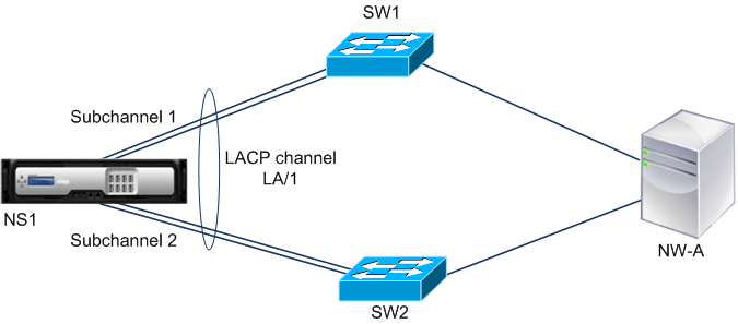
NS1 is connected to network device NW-A through SW1 and SW2. On NS1, LACP channel LA/1 is created from interfaces 1/1, 1/2, 1/3, and 1/4. Interfaces 1/1 and 1/2 of NS1 are connected to SW1, and interfaces 1/3 and 1/4 are connected to SW2. Each of the four links supports a maximum throughput of 1000Mbps. When the lrMinThroughput parameter is set to some value (say 2000), NS1 creates two logical subchannels from LA/1, one subchannel (say subchannel 1) using interfaces 1/1 and 1/2 (connected to SW1), and the other subchannel (subchannel 2) using interfaces 1/3 and 1/4 (connected to SW2).
NS1 applies an algorithm to make one subchannel (say subchannel 1) active and put the other on standby. NS1 and network device NW-A are accessible to each other through only the active subchannel.
Say subchannel 1 is active, and its maximum supported throughput falls below the lrMinThroughput value (for example, one of its links fails, and the maximum supported throughput falls to 1000 Mbps). Subchannel 2 becomes active and takes over.
Link Redundancy using LACP channels in a High Availability setup
In a high availability (HA) configuration, if you want to configure throughput (throughput parameter) based HA failover and link redundancy (lrMinThroughput parameter) on an LACP channel, you must set the throughput parameter to a value less than or equal to that of the lrMinThroughput parameter.
The maximum supported throughput of an LACP channel is calculated as the maximum supported throughput of the active subchannel.
If the throughput parameter value is equal to or less than the lrminthroughput parameter value, HA failover occurs when both of the following conditions exist at the same time:
-
None of the subchannels’ maximum supported throughput meet the lrMinThroughput parameter value.
-
The maximum supported throughput of the LACP channel does not meet the throughput parameter value
Consider an example of an HA setup that has NetScalers NS1 and NS2, with switches SW1 and SW2. NS1 is connected to NS2 through SW1 and SW2.
On NS1, LACP channel LA/1 is created from interfaces 1/1, 1/2, 1/3, and 1/4. Interfaces 1/1 and 1/2 of NS1 are connected to SW1, and interfaces 1/3 and 1/4 are connected to SW2. Each of the four links supports a maximum throughput of 1000 Mbps.
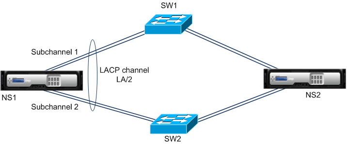
Following are the LACP-parameter settings in this example:
| Parameter | Value |
|---|---|
| Throughput | 2000 |
| lrminthroughput | 2000 |
NS1 forms two subchannels from LA/1, one subchannel (say subchannel 1) using interfaces 1/1 and 1/2 (connected to SW1), and the other subchannel (subchannel 2) using interfaces 1/3 and 1/4 (connected to SW2). Each of the two subchannels supports a maximum throughput of 2000 Mbps. Applying an algorithm, NS1 makes one subchannel (say subchannel 1) active and the other standby.
Say subchannel 1 is active, and its maximum supported throughput falls below the lrMinThroughput value (for example, one of its links fails, and maximum supported throughput falls to 1000 Mbps). Subchannel 2 becomes active and takes over. HA failover does not occur, because the maximum supported throughput of the LACP channel is not less than the throughput parameter value:
Maximum supported throughput of the LACP channel = Maximum supported throughput of the active channel = Maximum supported throughput of subchannel 2 = 2000 Mbps
If subchannel 2’s maximum supported throughput also falls below the lrminthroughput value (for example, one of its links fails, and the maximum supported throughput falls to 1000 Mbps), HA failover occurs, because the maximum supported throughput of the LACP channel is then less than the throughput parameter value:
Configure Link Redundancy using LACP channels
To configure link redundancy for a LACP channel by using the CLI:
At the command prompt, type the following commands to configure the channel and verify the configuration:
-
set channel \<id> -lrMinThroughput \<positive_integer>
-
show channel
Example:
> set channel la/1 –lrMinThroughput  2000
 Done
 > set channel la/2 –throughput 2000 –lrMinThroughput  2000
 Done
To configure link redundancy for a LACP channel by using GUI
-
Navigate to System > Network > Channels.
-
In the details pane, select an LACP channel for which you want to configure link redundancy, and then click Edit.
-
In the Configure LACP channel dialog box, set the lrMinThroughput parameter.
-
Click Close.